


Product Details
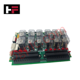
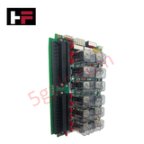
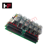
Configured for emergency trip logic and solenoid control in Mark VI turbine protection systems, the GE IS200TREGH1B (IS200TREGH1B Turbine Emergency Terminal Board) provides direct physical and electrical execution of turbine safety shutdown sequences.
Hardware Specifications
| Parameter | Specification |
|---|---|
| Model | IS200TREGH1B |
| Brand | General Electric |
| Origin | USA |
| Weight | 2.00 lbs |
| Dimensions | 17.8 cm x 33.02 cm |
| Operating Temp | 0 deg C to 70 deg C |
| Power Consumption | 200-250 VAC (Supply), 70-145 VDC (Bus) |
| Trip Channels | 6 (Total), 3 (Solenoid) |
Profinet / EtherNet/IP Deterministic Networks
The IS200TREGH1B serves as the primary interface for turbine emergency protection, interfacing directly with the QNX-based operating system to ensure deterministic trip execution. The module manages backplane bus communication velocity to meet the stringent latency requirements of turbine safety shutdown protocols. Firmware flash compatibility is managed via the Mark VI controller, ensuring that trip logic remains synchronized with system-wide safety parameters. The board supports I/O density scaling through its dedicated solenoid control circuitry, allowing for multi-channel trip solenoid operation. The interface is optimized to maintain high-integrity signal transmission, ensuring that the transition from a running state to a trip state is executed without delay or signal degradation.
Frequently Asked Questions
Q: Does the IS200TREGH1B terminal board support hot-swapping during turbine operation?
A: No. Any removal or replacement of the turbine emergency terminal board must be performed while the turbine system is in a controlled, non-operational state to avoid inadvertent trips or electrical damage.
Q: Is the bus voltage input (70-145 VDC) monitored by the Mark VI diagnostics?
A: Yes. The board provides status feedback to the Mark VI system, allowing for the monitoring of bus voltage health and identifying potential ground faults or power supply irregularities within the trip solenoid circuits.
Field Installation Guidelines
- Mounting: Install the board within the protection cabinet using the standard mounting hardware. Verify that the assembly is properly bonded to the cabinet ground to prevent electromagnetic noise from interfering with trip logic.
- Wiring: Terminate trip solenoid wiring to the designated output channels. Use high-integrity, shielded cabling for all emergency signal paths to ensure long-term stability and protection against interference.
- Voltage Verification: Before applying the 200-250 VAC supply or the 70-145 VDC bus voltage, verify all field wiring against the protection system schematic to ensure correct polarity and voltage matching.
- Environment: Maintain cabinet ambient temperature between 0 deg C and 70 deg C. Provide adequate airflow to prevent heat accumulation around the power input and switching circuits.
- Logic Verification: Following installation, perform a software-guided trip test to verify that all 3 trip solenoids respond correctly to emergency commands initiated from the Mark VI QNX-based controller.
Additional Information
- 100% Genuine Parts: All products are original and authentic, ensuring reliable industrial performance.
- 30-Day Refund Guarantee: Return any in-stock item within 30 days in original, unopened packaging for a full refund (excluding shipping and fees).
- 12-Month Warranty: Covers defects in materials or workmanship; excludes misuse, normal wear, or unauthorized modifications.
- Worldwide Shipping: We ship via USPS, UPS, FedEx, and DHL. Delivery times vary by country and may be subject to customs or import fees.
- Support & Contact: Technical and warranty assistance is available anytime. Contact us here: Contact.
- Purchase Guidance: Check product specifications and compatibility carefully before ordering to ensure proper application.


Tech & Buying Guide

Why 24V DC Power Supplies Standardize Modern Industrial Automation
Industrial control cabinets worldwide rely on 24V DC as the universal power standard for field instrumentation, sensors, and controllers. Walk into any manufacturing plant, and you will find PLCs, human-machine interfaces (HMIs), and smart actuators running on extra-low voltage DC. Standardizing on 24V DC enhances operational safety, lowers cabinet footprint, and maintains steady control performance across factory networks.

Essential Motion Control Commands: A Practical Guide for Engineers
Automation engineers often rely on precise position and speed control to drive modern factory machinery. Modern industrial systems, such as Programmable Logic Controllers (PLCs) and Distributed Control Systems (DCS), depend heavily on standardized motion instructions. Mastering these commands ensures operational safety, protects mechanical components, and optimizes cycle times across production lines.

Mastering Modern Industrial Joystick Controls in Heavy Automation
Industrial joysticks play a pivotal role in human-machine interaction across heavy material handling and mobile hydraulics. These tactile controllers translate complex operator movements into precise electrical signals for PLCs, motion controllers, and DCS networks. Consequently, selecting and installing the right joystick architecture ensures operator safety, reduces fatigue, and optimizes equipment performance.