


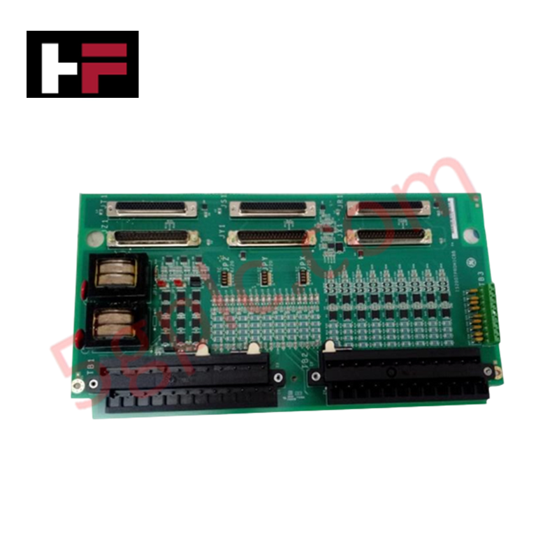
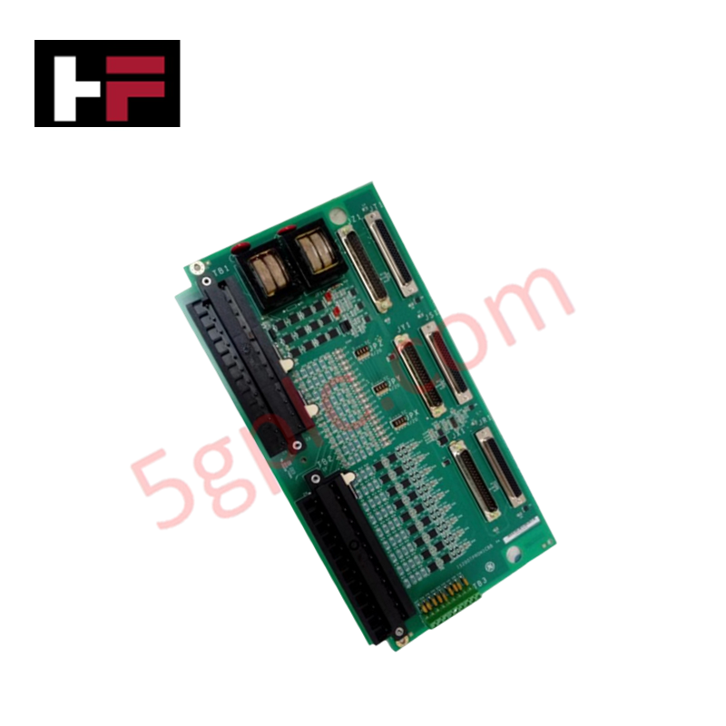


Product Details
Configured for emergency trip logic and signal conditioning in Mark VIe turbine control architectures, the GE IS200TPROH1C (IS200TPROH1C Emergency Protection Terminal Board) provides direct physical and electrical execution of bus/generator voltage monitoring and speed signal routing.
Hardware Specifications
| Parameter | Specification |
|---|---|
| Model | IS200TPROH1C |
| Brand | General Electric |
| Origin | USA |
| Weight | Standard terminal board assembly |
| Dimensions | Mark VIe standard form factor |
| Operating Temp | Industrial rated range |
| Power Consumption | System-bus dependent |
| I/O Capacity | 3 x PPRO I/O packs |
| Inputs | PT bus and generator voltage, speed signals |
Profinet / EtherNet/IP Deterministic Networks
The IS200TPROH1C integrates into the Mark VIe platform to support high-speed emergency trip sequences. The board facilitates backplane bus communication velocity by interfacing directly with three PPRO I/O packs, ensuring deterministic processing of generator voltage and speed inputs. Firmware flash compatibility is managed via the PPRO packs to maintain alignment with the turbine protection logic. The terminal board architecture supports I/O density scaling through its dual 24-terminal pluggable blocks, allowing for flexible field wiring while maintaining electrical isolation between voltage inputs and the protection circuitry. The onboard metal-oxide varistors (MOVs) provide surge protection; however, users must ensure segregation between 240 VAC and DC potentials to prevent exceeding MOV peak voltage ratings.
Frequently Asked Questions
Q: Can the IS200TPROH1C be hot-swapped while the turbine control system is active?
A: No. Any maintenance or replacement of the TPRO board requires the system to be de-energized to prevent accidental trip signal activation or electrical damage to the PPRO I/O pack interfaces.
Q: What are the risks of cross-connecting 125 VDC and 240 VAC circuits on this board?
A: An inadvertent connection between these potentials causes the sum of the AC peak voltage and DC voltage to be applied across the protection MOVs. This exceeds the specified rating and leads to component failure.
Field Installation Guidelines
- Mounting: Secure the board within the control cabinet. Ensure the chassis ground is firmly connected to provide a return path for surge currents through the integrated MOV protection circuitry.
- Wiring: Terminate field signals to the two 24-terminal blocks. Strictly observe wire gauge limits and segregation requirements to avoid crossing 240 VAC and DC signals.
- Connectivity: Ensure the three DC-37 connectors are fully seated and locked. These cables facilitate communication to the backup trip relay terminal boards.
- Environment: Verify that the cabinet environment is controlled to prevent moisture or corrosive dust from compromising the barrier terminals.
- Verification: Prior to commissioning, perform a point-to-point check of the PT inputs and speed signals. Ensure the PPRO I/O packs correctly interpret the signal scaling as defined in the system toolbox.
Additional Information
- 100% Genuine Parts: All products are original and authentic, ensuring reliable industrial performance.
- 30-Day Refund Guarantee: Return any in-stock item within 30 days in original, unopened packaging for a full refund (excluding shipping and fees).
- 12-Month Warranty: Covers defects in materials or workmanship; excludes misuse, normal wear, or unauthorized modifications.
- Worldwide Shipping: We ship via USPS, UPS, FedEx, and DHL. Delivery times vary by country and may be subject to customs or import fees.
- Support & Contact: Technical and warranty assistance is available anytime. Contact us here: Contact.
- Purchase Guidance: Check product specifications and compatibility carefully before ordering to ensure proper application.


Tech & Buying Guide

Why 24V DC Power Supplies Standardize Modern Industrial Automation
Industrial control cabinets worldwide rely on 24V DC as the universal power standard for field instrumentation, sensors, and controllers. Walk into any manufacturing plant, and you will find PLCs, human-machine interfaces (HMIs), and smart actuators running on extra-low voltage DC. Standardizing on 24V DC enhances operational safety, lowers cabinet footprint, and maintains steady control performance across factory networks.

Essential Motion Control Commands: A Practical Guide for Engineers
Automation engineers often rely on precise position and speed control to drive modern factory machinery. Modern industrial systems, such as Programmable Logic Controllers (PLCs) and Distributed Control Systems (DCS), depend heavily on standardized motion instructions. Mastering these commands ensures operational safety, protects mechanical components, and optimizes cycle times across production lines.

Mastering Modern Industrial Joystick Controls in Heavy Automation
Industrial joysticks play a pivotal role in human-machine interaction across heavy material handling and mobile hydraulics. These tactile controllers translate complex operator movements into precise electrical signals for PLCs, motion controllers, and DCS networks. Consequently, selecting and installing the right joystick architecture ensures operator safety, reduces fatigue, and optimizes equipment performance.