


Product Details
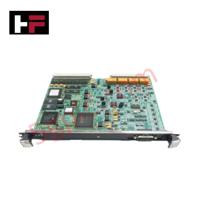
Configured for electro-hydraulic servo control and LVDT position feedback processing in Mark VI turbine control systems, the GE IS200VSVOH1B (IS200VSVOH1B VME Servo Control Board) provides direct physical and electrical execution of valve control algorithms and multi-channel servo actuation.
Hardware Specifications
| Parameter | Specification |
|---|---|
| Model | IS200VSVOH1B |
| Brand | General Electric |
| Origin | USA |
| Weight | Standard VME board assembly |
| Dimensions | Mark VI standard VME form factor |
| Operating Temp | Industrial rated range |
| Power Consumption | System-bus dependent |
| Control Capacity | 4 x Electro-hydraulic servovalves |
| Feedback | LVDT inputs |
Profinet / EtherNet/IP Deterministic Networks
The VSVO board functions as the primary controller for four electro-hydraulic servovalves, maintaining backplane bus communication velocity through deterministic integration within the VME rack. The module executes internal loop control algorithms to manage valve positioning, utilizing LVDT feedback to ensure high-accuracy control. Firmware flash compatibility is facilitated via the Mark VI controller, allowing for optimized valve positioning responses. I/O density scaling is achieved through modular terminal board interfacing, where the VSVO communicates with TSVO or DSVO boards to route signals in either simplex or Triple Modular Redundant (TMR) configurations.
Frequently Asked Questions
Q: Is the IS200VSVOH1B hot-swappable while the Mark VI system is powered?
A: No. System power must be removed before installing or removing the board from the VME rack to avoid electrical faults on the servovalve control circuits and backplane bus.
Q: How are external trip signals handled by the VSVO module?
A: The board interfaces with protection modules via the JD1 and JD2 plugs. These inputs provide direct hardware-level overrides to ensure fail-safe state execution for the controlled steam or fuel valves.
Field Installation Guidelines
- Mounting: Carefully insert the VSVO module into the assigned VME rack slot, ensuring the backplane pins are correctly engaged. Secure the module using the faceplate fastening screws to prevent vibration-induced disconnection.
- Connectivity: Connect the control cables to the J5 plug and the rack J3/J4 connectors. For TMR applications, ensure that the JR1, JS1, and JT1 connectors are utilized to fan out the control signals consistently across the redundant paths.
- Trip Integration: Terminate external trip wiring to the JD1 or JD2 ports. Confirm signal logic states before transitioning the system to operational mode to ensure the protection trip paths are active.
- Environment: Verify that the control cabinet environment is free of excessive conductive dust or humidity that could affect the surface-mount circuitry. Maintain cabinet temperatures within the specified industrial operating range.
- Verification: Prior to initiating turbine fuel control, perform a software-directed stroke check. Validate that the LVDT feedback signals accurately reflect valve position and that the servo current output is calibrated to the valve manufacturer's operational setpoints.
Additional Information
- 100% Genuine Parts: All products are original and authentic, ensuring reliable industrial performance.
- 30-Day Refund Guarantee: Return any in-stock item within 30 days in original, unopened packaging for a full refund (excluding shipping and fees).
- 12-Month Warranty: Covers defects in materials or workmanship; excludes misuse, normal wear, or unauthorized modifications.
- Worldwide Shipping: We ship via USPS, UPS, FedEx, and DHL. Delivery times vary by country and may be subject to customs or import fees.
- Support & Contact: Technical and warranty assistance is available anytime. Contact us here: Contact.
- Purchase Guidance: Check product specifications and compatibility carefully before ordering to ensure proper application.


Tech & Buying Guide

Why 24V DC Power Supplies Standardize Modern Industrial Automation
Industrial control cabinets worldwide rely on 24V DC as the universal power standard for field instrumentation, sensors, and controllers. Walk into any manufacturing plant, and you will find PLCs, human-machine interfaces (HMIs), and smart actuators running on extra-low voltage DC. Standardizing on 24V DC enhances operational safety, lowers cabinet footprint, and maintains steady control performance across factory networks.

Essential Motion Control Commands: A Practical Guide for Engineers
Automation engineers often rely on precise position and speed control to drive modern factory machinery. Modern industrial systems, such as Programmable Logic Controllers (PLCs) and Distributed Control Systems (DCS), depend heavily on standardized motion instructions. Mastering these commands ensures operational safety, protects mechanical components, and optimizes cycle times across production lines.

Mastering Modern Industrial Joystick Controls in Heavy Automation
Industrial joysticks play a pivotal role in human-machine interaction across heavy material handling and mobile hydraulics. These tactile controllers translate complex operator movements into precise electrical signals for PLCs, motion controllers, and DCS networks. Consequently, selecting and installing the right joystick architecture ensures operator safety, reduces fatigue, and optimizes equipment performance.