


Product Details
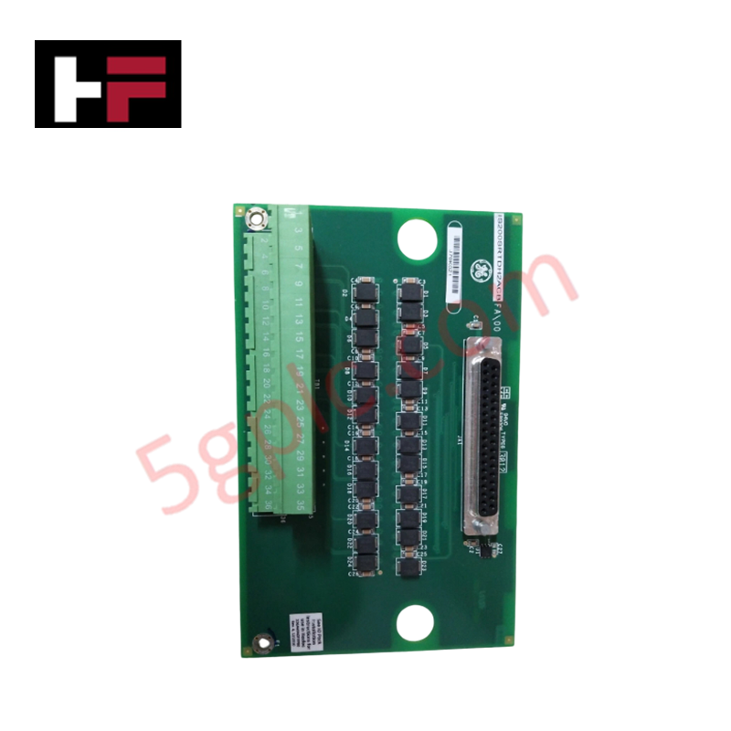
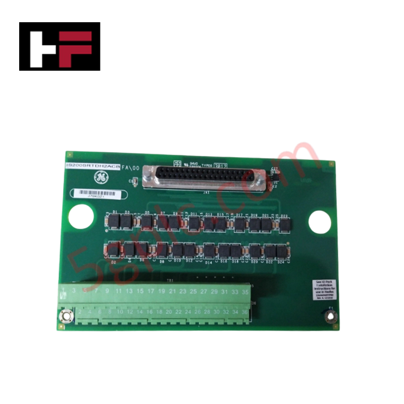
The GE IS200SRTDH2ACB, also cataloged as the IS200SRTDH2ACB RTD Input Terminal Board, operates as a dedicated hardware component for temperature sensor signal acquisition and conditioning within Mark VIe control platforms.
Hardware Specifications
| Parameter | Specification |
|---|---|
| Model | IS200SRTDH2ACB |
| Brand | General Electric |
| Origin | USA |
| Weight | 0.6 kg |
| Dimensions | 16.7 cm x 14.8 cm x 5.5 cm |
| Operating Temp | Industrial rated range |
| Power Consumption | System-bus dependent |
| Product Type | RTD Input Terminal Board |
| Technology | Printed circuit board |
Profinet / EtherNet/IP Deterministic Networks
The IS200SRTDH2ACB module manages backplane bus communication velocity by facilitating the conversion of resistance temperature detector (RTD) analog inputs into digital signals for processing by the I/O pack. The board maintains deterministic signal integrity, ensuring that temperature data remains synchronized with the controller's scan cycle. Firmware flash compatibility is governed by the associated I/O pack, which monitors the terminal board's status and ensures the validity of sensor readings. I/O density scaling is supported through standard terminal block arrangements, providing a localized interface for multiple RTD channels while isolating sensitive signal paths from high-power electromagnetic interference within the control cabinet.
Frequently Asked Questions
Q: Is the IS200SRTDH2ACB board hot-swappable during system operation?
A: No. Replacement requires the associated I/O pack to be de-energized to prevent current spikes or potential damage to the RTD input circuitry during the removal or installation process.
Q: How is signal shielding handled on the IS200SRTDH2ACB?
A: The board provides dedicated terminals for sensor shield termination. Shields must be connected to the cabinet ground bus at the terminal board to minimize noise pickup and maintain measurement accuracy.
Field Installation Guidelines
- Mounting: Install the board in a clean, dry location within the control cabinet. Ensure the mounting surfaces are free of debris to prevent mechanical stress on the printed circuit board.
- Wiring: Terminate RTD leads to the terminal blocks according to the system wiring diagram. Ensure that 3-wire RTD configurations are correctly mapped to provide lead-resistance compensation.
- Grounding: Bond the board chassis to the cabinet ground using the designated earthing points. Verify that the shield termination strip has a low-impedance path to the system ground.
- Environment: Verify that ambient temperatures remain within specified industrial operating limits. Prevent exposure to condensation or corrosive environments that could degrade signal terminal contacts.
- Verification: Prior to system integration, use a calibrated resistor simulator to verify the input channel accuracy for each RTD point, confirming that the digital value reported by the controller matches the input resistance.
Additional Information
- 100% Genuine Parts: All products are original and authentic, ensuring reliable industrial performance.
- 30-Day Refund Guarantee: Return any in-stock item within 30 days in original, unopened packaging for a full refund (excluding shipping and fees).
- 12-Month Warranty: Covers defects in materials or workmanship; excludes misuse, normal wear, or unauthorized modifications.
- Worldwide Shipping: We ship via USPS, UPS, FedEx, and DHL. Delivery times vary by country and may be subject to customs or import fees.
- Support & Contact: Technical and warranty assistance is available anytime. Contact us here: Contact.
- Purchase Guidance: Check product specifications and compatibility carefully before ordering to ensure proper application.


Tech & Buying Guide

Why 24V DC Power Supplies Standardize Modern Industrial Automation
Industrial control cabinets worldwide rely on 24V DC as the universal power standard for field instrumentation, sensors, and controllers. Walk into any manufacturing plant, and you will find PLCs, human-machine interfaces (HMIs), and smart actuators running on extra-low voltage DC. Standardizing on 24V DC enhances operational safety, lowers cabinet footprint, and maintains steady control performance across factory networks.

Essential Motion Control Commands: A Practical Guide for Engineers
Automation engineers often rely on precise position and speed control to drive modern factory machinery. Modern industrial systems, such as Programmable Logic Controllers (PLCs) and Distributed Control Systems (DCS), depend heavily on standardized motion instructions. Mastering these commands ensures operational safety, protects mechanical components, and optimizes cycle times across production lines.

Mastering Modern Industrial Joystick Controls in Heavy Automation
Industrial joysticks play a pivotal role in human-machine interaction across heavy material handling and mobile hydraulics. These tactile controllers translate complex operator movements into precise electrical signals for PLCs, motion controllers, and DCS networks. Consequently, selecting and installing the right joystick architecture ensures operator safety, reduces fatigue, and optimizes equipment performance.