


Product Details
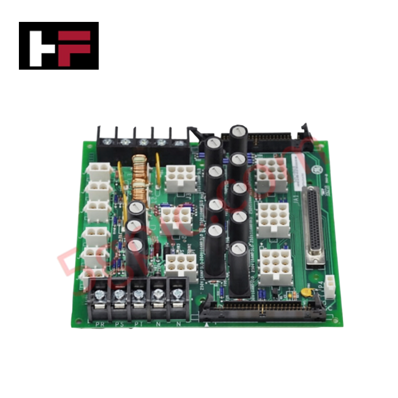
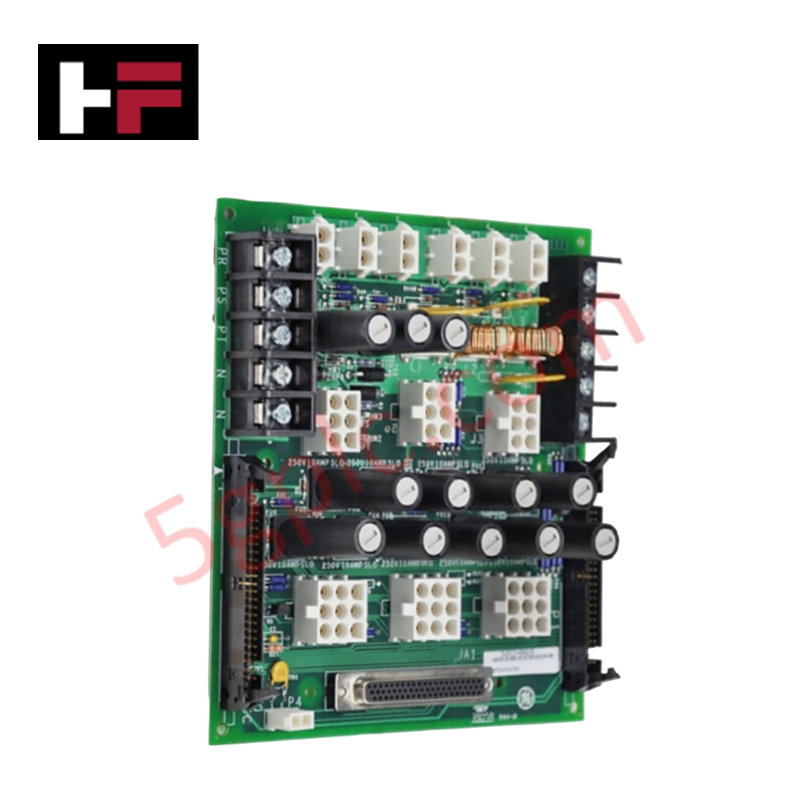
Configured for power regulation and distribution in Mark VIe turbine control architectures, the GE IS200JPDMG1A (IS200JPDMG1A Power Distribution Board) provides direct physical and electrical execution of 28 VDC input voltage distribution to system-level components.
Hardware Specifications
| Parameter | Specification |
|---|---|
| Model | IS200JPDMG1A |
| Brand | General Electric |
| Origin | USA |
| Weight | Standard PCB assembly |
| Dimensions | 16.51 cm x 17.8 cm |
| Operating Temp | -30 deg C to 65 deg C |
| Power Consumption | 28 VDC Input |
| Mounting | DIN-rail mounting |
Profinet / EtherNet/IP Deterministic Networks
The IS200JPDMG1A serves as a critical distribution node for the Mark VIe platform, maintaining backplane bus communication velocity by ensuring stable voltage levels across distributed I/O packs. The module's hardware architecture is designed for I/O density scaling, allowing for efficient branching of power to multiple control modules. Firmware flash compatibility is handled by the upstream power converters, while the JPDM board provides localized surge protection and voltage stability. In deterministic network environments, the module acts as a passive distribution point that maintains power consistency, preventing signal attenuation or logic faults that could otherwise be induced by voltage fluctuations on the 28 VDC rail.
Frequently Asked Questions
Q: Is the IS200JPDMG1A board hot-swappable while the Mark VIe system is active?
A: No. The board must be fully isolated from the 28 VDC input supply before installation or removal to prevent potential damage to the distribution bus or connected downstream modules.
Q: How is the JPDM board verified for hazardous location compliance?
A: The board is rated for Class 1, Division 2 explosive atmospheres. Ensure that the DIN-rail mounting provides a secure, vibration-resistant connection and that all wiring meets the relevant hazardous location installation codes.
Field Installation Guidelines
- Mounting: Secure the board onto the standard DIN-rail within the control cabinet. Ensure the mounting is stable to prevent vibration-induced stress on the terminal connections.
- Wiring: Connect the 28 VDC input from the external AC/DC or DC/DC converter. Use conductors sized according to the total current load to minimize voltage drops across the distribution network.
- Shielding: Ensure all field wiring shields are grounded at the cabinet ground bus. Proper grounding is necessary to mitigate electromagnetic interference and maintain the integrity of the 28 VDC distribution bus.
- Environment: Operate the module within the -30 deg C to 65 deg C range. Ensure that ambient air flow is not restricted, especially in Class 1, Division 2 installations, to prevent heat accumulation near the power circuits.
- Verification: Prior to system start-up, measure the output voltage at the distribution terminals using a calibrated multimeter to confirm that the 28 VDC input is correctly distributed to all connected control modules.
Additional Information
- 100% Genuine Parts: All products are original and authentic, ensuring reliable industrial performance.
- 30-Day Refund Guarantee: Return any in-stock item within 30 days in original, unopened packaging for a full refund (excluding shipping and fees).
- 12-Month Warranty: Covers defects in materials or workmanship; excludes misuse, normal wear, or unauthorized modifications.
- Worldwide Shipping: We ship via USPS, UPS, FedEx, and DHL. Delivery times vary by country and may be subject to customs or import fees.
- Support & Contact: Technical and warranty assistance is available anytime. Contact us here: Contact.
- Purchase Guidance: Check product specifications and compatibility carefully before ordering to ensure proper application.


Tech & Buying Guide

Why 24V DC Power Supplies Standardize Modern Industrial Automation
Industrial control cabinets worldwide rely on 24V DC as the universal power standard for field instrumentation, sensors, and controllers. Walk into any manufacturing plant, and you will find PLCs, human-machine interfaces (HMIs), and smart actuators running on extra-low voltage DC. Standardizing on 24V DC enhances operational safety, lowers cabinet footprint, and maintains steady control performance across factory networks.

Essential Motion Control Commands: A Practical Guide for Engineers
Automation engineers often rely on precise position and speed control to drive modern factory machinery. Modern industrial systems, such as Programmable Logic Controllers (PLCs) and Distributed Control Systems (DCS), depend heavily on standardized motion instructions. Mastering these commands ensures operational safety, protects mechanical components, and optimizes cycle times across production lines.

Mastering Modern Industrial Joystick Controls in Heavy Automation
Industrial joysticks play a pivotal role in human-machine interaction across heavy material handling and mobile hydraulics. These tactile controllers translate complex operator movements into precise electrical signals for PLCs, motion controllers, and DCS networks. Consequently, selecting and installing the right joystick architecture ensures operator safety, reduces fatigue, and optimizes equipment performance.