










Product Details
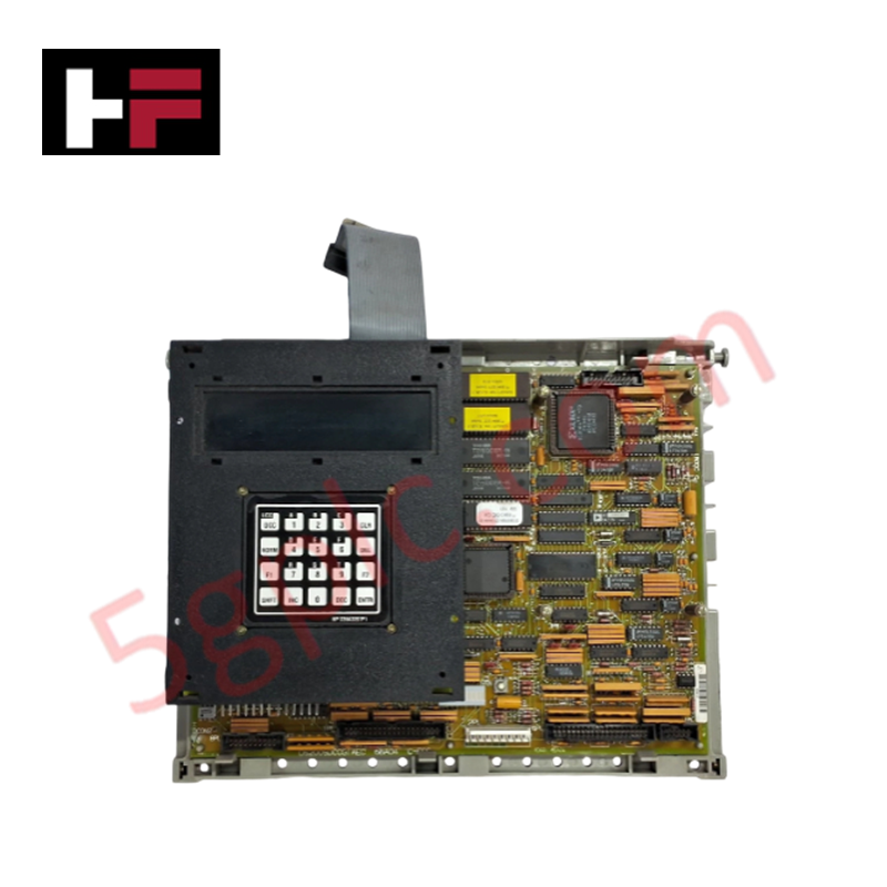
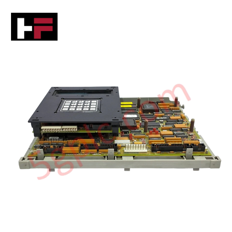
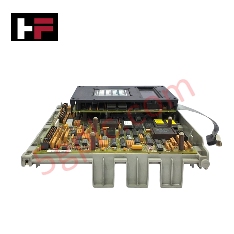
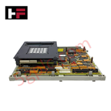
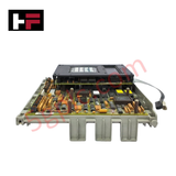
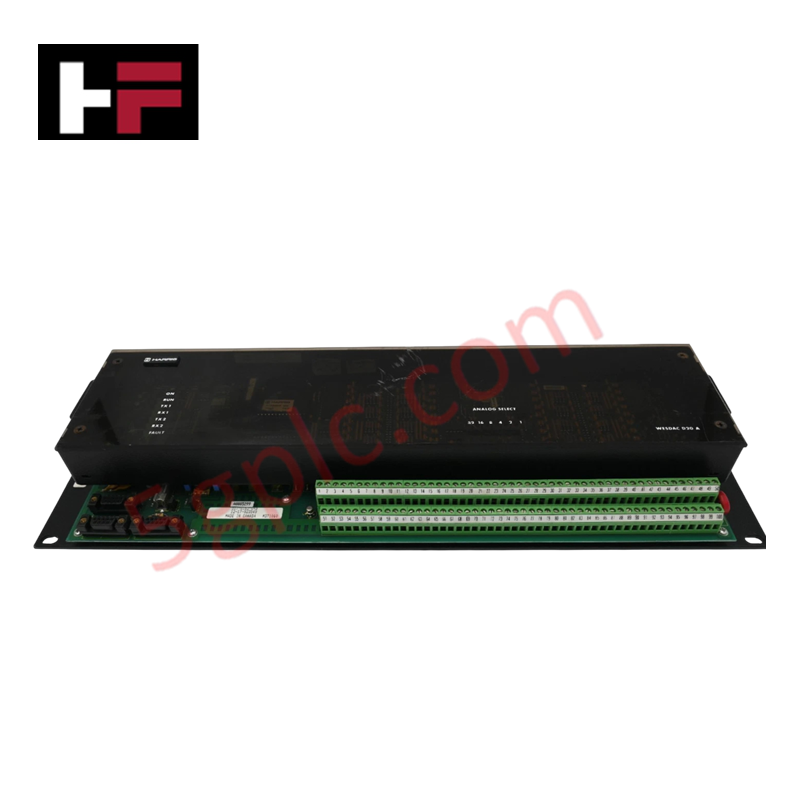
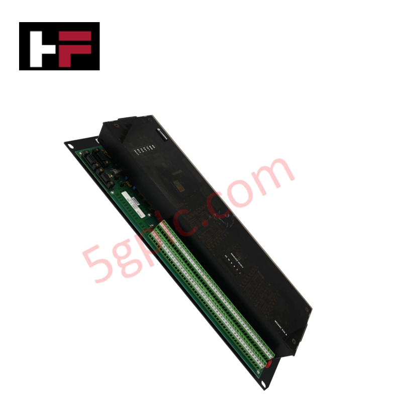
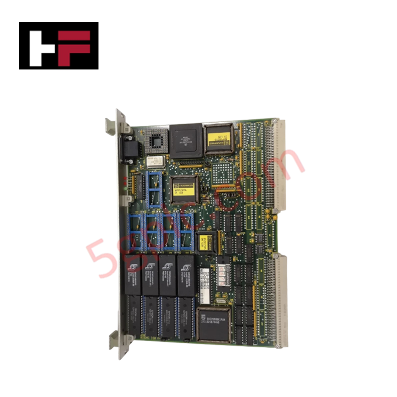
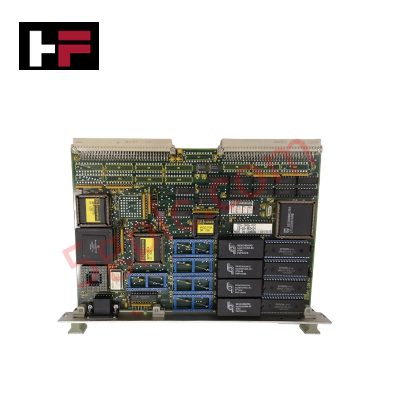
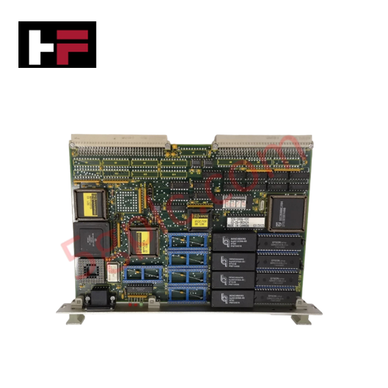
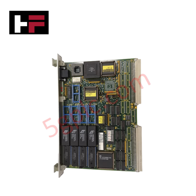
The GE DS200SDCCG1AEC, also cataloged as the DS200SDCCG1 Drive Control Card, operates as a dedicated hardware component for motor regulation and control loop execution within Mark V Speedtronic turbine control systems.
Hardware Specifications
| Parameter | Specification |
|---|---|
| Model | DS200SDCCG1AEC |
| Brand | General Electric |
| Origin | USA |
| Weight | Not specified |
| Core Components | 3 microprocessors, dual-ported RAM, 10-LED diagnostic array |
Industrial Control & Firmware Compatibility
The DS200SDCCG1AEC utilizes a tri-processor architecture to execute real-time drive management. Deterministic network performance is contingent upon backplane bus communication velocity, ensuring synchronized data exchange between the processors and auxiliary interface cards (SLCC, LCC, SPC, PSCB). Firmware flash compatibility requires strict adherence to system-level version parity; mismatched firmware may result in processing latencies or synchronization errors during I/O density scaling operations. Diagnostic data extraction is supported via serial connection, allowing operators to download system variables and fault logs to an external host for analysis.
Frequently Asked Questions
Q: How are diagnostic error codes interpreted via the onboard LED array?
A: The ten-LED row provides status feedback through flash frequency. A sequential, continuous left-to-right pattern indicates normal operation. Slow-frequency flashing represents error codes 1 to 399, while high-frequency flashing corresponds to error codes 400 to 1023.
Q: Are there specific requirements for accessing onboard test points?
A: Yes. The board features metallic test posts for signal path verification. Testing must be performed exclusively by authorized personnel using calibrated equipment to prevent signal interference or accidental grounding of sensitive control circuitry.
Field Installation Guidelines
- Safety Protocol: De-energize the drive cabinet completely before accessing internal components. Ensure that the drive is in a zero-energy state to prevent electrical shock from high-voltage circuits.
- ESD Protection: Use certified anti-static wrist straps and conductive work surfaces when handling the PCB. The onboard microprocessors are susceptible to damage from electrostatic discharge during installation or probing.
- Physical Alignment: When seating the card into the drive rack, ensure alignment with the backplane connectors. Do not force the board, as misalignment can damage the connector pins or the backplane interface.
- Verification: Post-installation, monitor the LED sequence across the row. Absence of a sequential flashing pattern upon power-up indicates a potential initialization failure or incorrect board seating; immediately verify backplane connectivity and system-level configuration parameters.
Additional Information
- 100% Genuine Parts: All products are original and authentic, ensuring reliable industrial performance.
- 30-Day Refund Guarantee: Return any in-stock item within 30 days in original, unopened packaging for a full refund (excluding shipping and fees).
- 12-Month Warranty: Covers defects in materials or workmanship; excludes misuse, normal wear, or unauthorized modifications.
- Worldwide Shipping: We ship via USPS, UPS, FedEx, and DHL. Delivery times vary by country and may be subject to customs or import fees.
- Support & Contact: Technical and warranty assistance is available anytime. Contact us here: Contact.
- Purchase Guidance: Check product specifications and compatibility carefully before ordering to ensure proper application.
Tech & Buying Guide

Why 24V DC Power Supplies Standardize Modern Industrial Automation
Industrial control cabinets worldwide rely on 24V DC as the universal power standard for field instrumentation, sensors, and controllers. Walk into any manufacturing plant, and you will find PLCs, human-machine interfaces (HMIs), and smart actuators running on extra-low voltage DC. Standardizing on 24V DC enhances operational safety, lowers cabinet footprint, and maintains steady control performance across factory networks.

Essential Motion Control Commands: A Practical Guide for Engineers
Automation engineers often rely on precise position and speed control to drive modern factory machinery. Modern industrial systems, such as Programmable Logic Controllers (PLCs) and Distributed Control Systems (DCS), depend heavily on standardized motion instructions. Mastering these commands ensures operational safety, protects mechanical components, and optimizes cycle times across production lines.
Mastering Modern Industrial Joystick Controls in Heavy Automation
Industrial joysticks play a pivotal role in human-machine interaction across heavy material handling and mobile hydraulics. These tactile controllers translate complex operator movements into precise electrical signals for PLCs, motion controllers, and DCS networks. Consequently, selecting and installing the right joystick architecture ensures operator safety, reduces fatigue, and optimizes equipment performance.