


Product Details
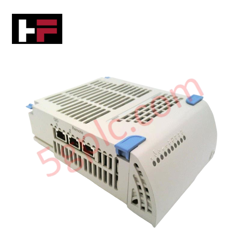
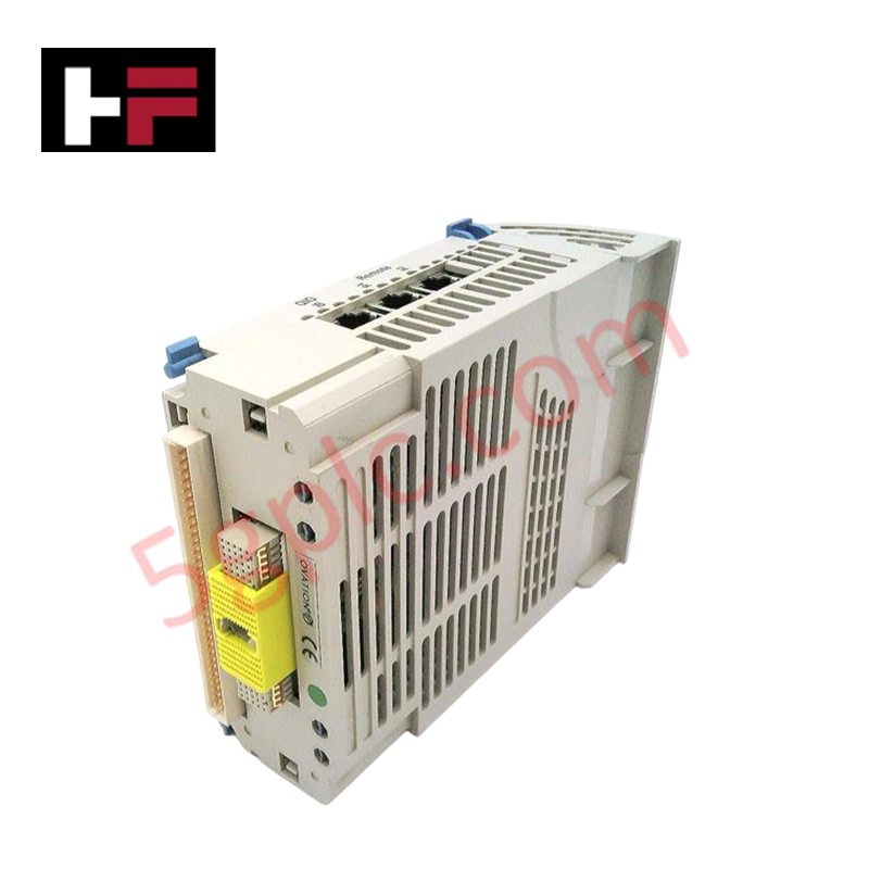
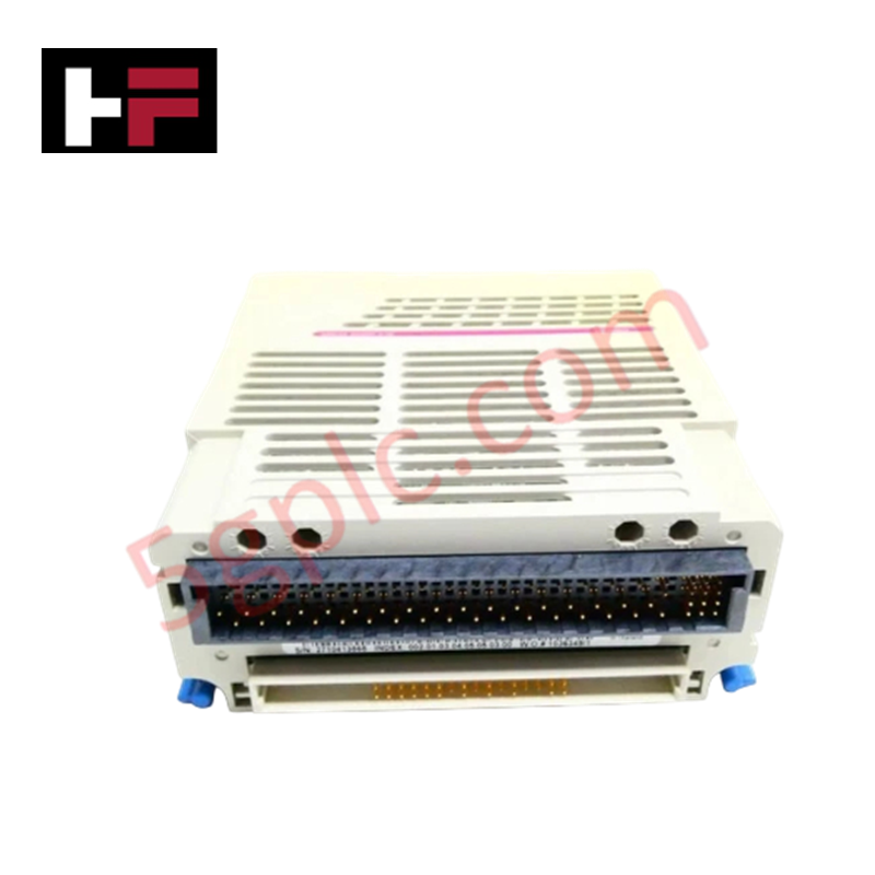
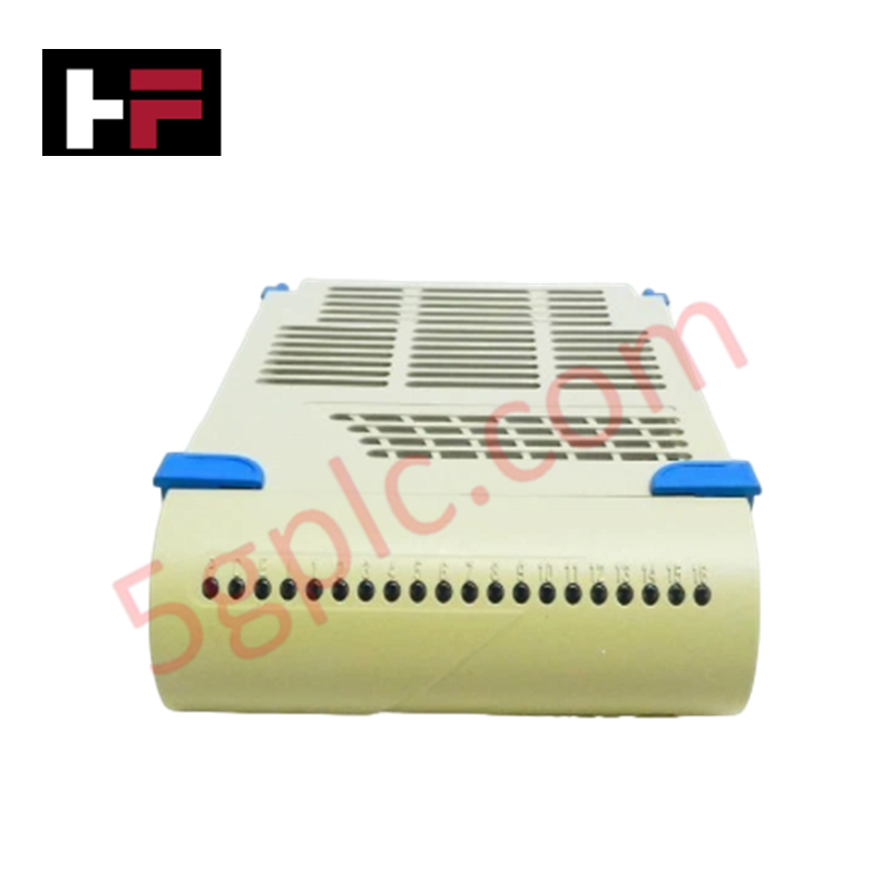
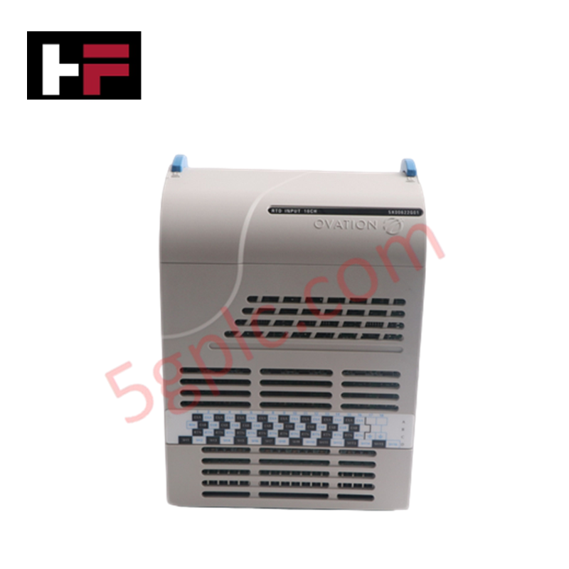
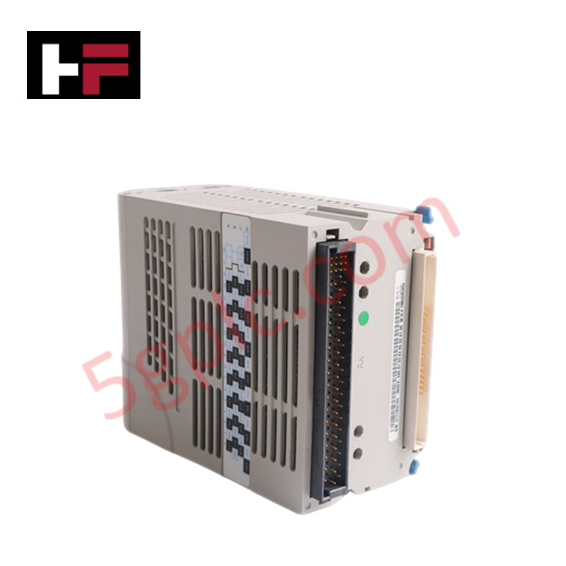
Configured for high-speed event capture in Ovation control networks, the Westinghouse Ovation 5X00357G01 (5X00357G01) Digital I/O Module provides direct physical electrical execution for monitoring 16 differential input channels. The module processes 24 VDC inputs from field devices including switches, alarms, and discrete sensors, utilizing programmable event filters to mitigate signal noise.
Hardware Specifications
| Parameter | Specification |
|---|---|
| Model | 5X00357G01 |
| Brand | Westinghouse |
| Origin | USA |
| Weight | 0.35 kg |
| Dimensions | 150 mm x 20 mm x 190 mm |
| Operating Temp | -40 to 70 deg C |
| Power Consumption | < 10 W |
| Input Type | 16 Differential Channels (24 VDC) |
Channel-to-Channel Isolation
The 5X00357G01 employs galvanic channel-to-channel isolation to maintain signal integrity and prevent common-mode noise propagation between discrete input loops. This isolation architecture is necessary to preserve the accuracy of event timestamps and prevents electrical ground potential differences from affecting the logic state detection across the 16 channels. Each channel includes hardware-level break detection to monitor loop continuity, ensuring that field-side open or short circuit conditions are identified and reported to the controller without impacting adjacent channel operations.
Frequently Asked Questions (FAQ)
Q: Does this module support redundant configuration for high-availability applications?
A: Yes, the 5X00357G01 supports configuration in redundant pairs. In such setups, the secondary module remains in a synchronized state to ensure seamless transition if the primary module experiences a hardware fault.
Q: How do the programmable event filters function?
A: The event filters are configurable via the Ovation controller software; they allow for the definition of debounce times to suppress high-frequency noise or contact bounce, ensuring that only valid, stable state changes are recorded as events.
Field Installation Guidelines
- Ensure the I/O chassis is de-energized before inserting the module into the backplane to prevent contact arcing.
- Align the module with the chassis guide rails and push firmly until the locking lever fully engages the connector.
- Terminate 24 VDC field wiring at the I/O terminal block, ensuring that twisted-pair cabling is used for all differential signal paths to minimize electromagnetic interference.
- Connect the cable shield drain wire to the cabinet ground bus at a single common point to prevent the formation of ground loops.
- Verify per-channel LED indicators during system commissioning to confirm that field status transitions are accurately reflected in the control software.
Additional Information
- 100% Genuine Parts: All products are original and authentic, ensuring reliable industrial performance.
- 30-Day Refund Guarantee: Return any in-stock item within 30 days in original, unopened packaging for a full refund (excluding shipping and fees).
- 12-Month Warranty: Covers defects in materials or workmanship; excludes misuse, normal wear, or unauthorized modifications.
- Worldwide Shipping: We ship via USPS, UPS, FedEx, and DHL. Delivery times vary by country and may be subject to customs or import fees.
- Support & Contact: Technical and warranty assistance is available anytime. Contact us here: Contact.
- Purchase Guidance: Check product specifications and compatibility carefully before ordering to ensure proper application.


Tech & Buying Guide

Why 24V DC Power Supplies Standardize Modern Industrial Automation
Industrial control cabinets worldwide rely on 24V DC as the universal power standard for field instrumentation, sensors, and controllers. Walk into any manufacturing plant, and you will find PLCs, human-machine interfaces (HMIs), and smart actuators running on extra-low voltage DC. Standardizing on 24V DC enhances operational safety, lowers cabinet footprint, and maintains steady control performance across factory networks.

Essential Motion Control Commands: A Practical Guide for Engineers
Automation engineers often rely on precise position and speed control to drive modern factory machinery. Modern industrial systems, such as Programmable Logic Controllers (PLCs) and Distributed Control Systems (DCS), depend heavily on standardized motion instructions. Mastering these commands ensures operational safety, protects mechanical components, and optimizes cycle times across production lines.

Mastering Modern Industrial Joystick Controls in Heavy Automation
Industrial joysticks play a pivotal role in human-machine interaction across heavy material handling and mobile hydraulics. These tactile controllers translate complex operator movements into precise electrical signals for PLCs, motion controllers, and DCS networks. Consequently, selecting and installing the right joystick architecture ensures operator safety, reduces fatigue, and optimizes equipment performance.