


Product Details
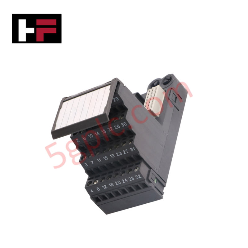
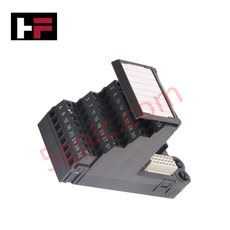
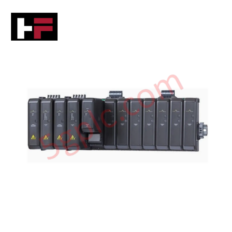
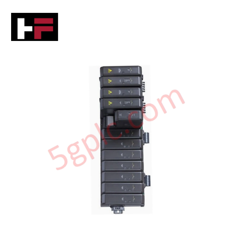
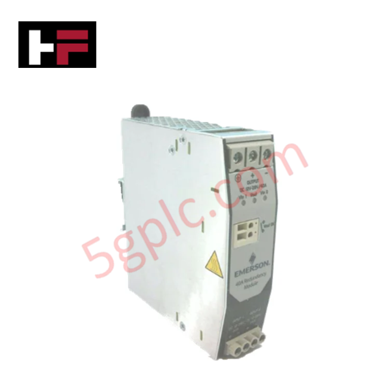
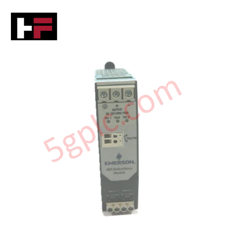
Configured for high-density field wiring integration within DeltaV DCS platforms, the Emerson KJ4006X1-BL1 (KJ4006X1-BL1 Terminal Block) provides direct physical signal termination for 8 analog input channels with user-configurable 2/4-wire support.
Hardware Specifications
| Parameter | Specification |
|---|---|
| Model | KJ4006X1-BL1 |
| Brand | Emerson |
| Origin | Subject to factory shipping documentation |
| Weight | 0.2 kg |
| Dimensions | 100 mm x 50 mm x 25 mm |
| Operating Temp | -40 deg C to 70 deg C |
| Power Consumption | Passive interconnect component |
| Channels | 8 Analog Input Channels |
| Signal Range | -10 V to +10 V or 4 mA to 20 mA |
| Input Impedance | 10 kO (typical) |
| Isolation Voltage | 1500 VDC between channels and field power |
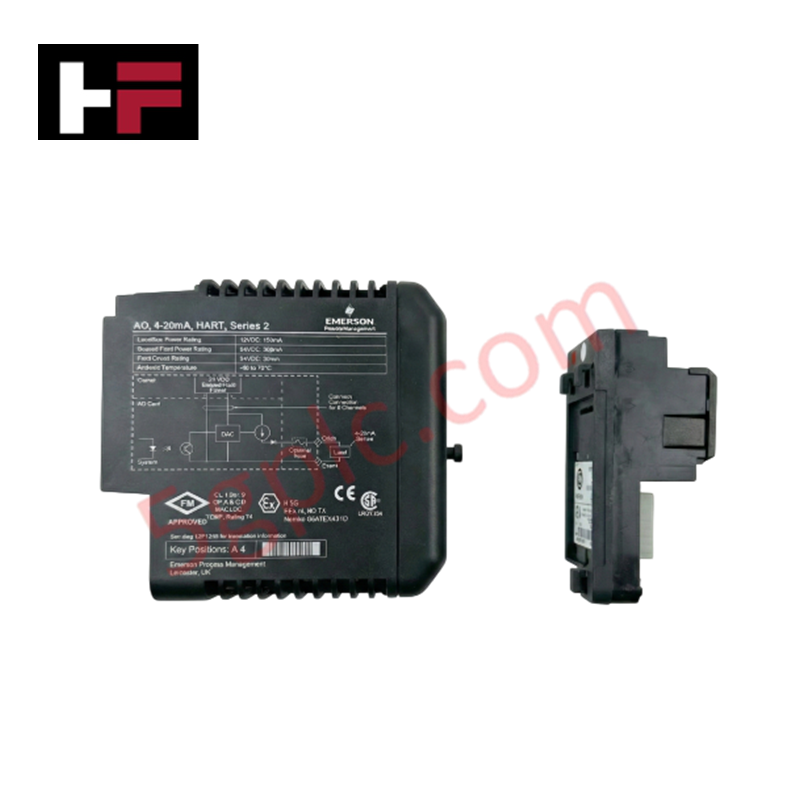
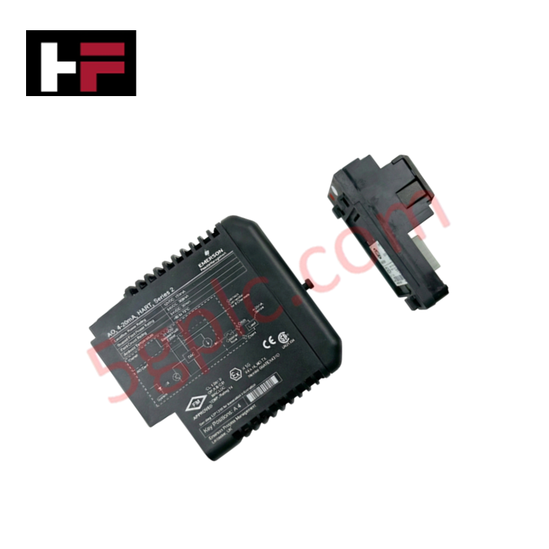
4-20 mA HART Loop Protocol Connectivity
The KJ4006X1-BL1 acts as the primary interface module for field instrumentation in DeltaV systems, supporting both voltage and current signaling. The terminal block is designed to accommodate 4-20 mA HART loop protocol signals, enabling seamless communication between smart field transmitters and the DCS controller. The architecture ensures 1500 VDC isolation between individual channels and the field power supply, minimizing the risk of ground loops and common-mode interference. This passive termination design maintains signal loop integrity while conforming to the ISA-S71.04 Class G3 standard for airborne contaminants, ensuring longevity in harsh process environments.
Frequently Asked Questions
Q: Is this terminal block compatible with both 2-wire and 4-wire field device configurations?
A: Yes. The terminal block is user-configurable to support both 2-wire and 4-wire analog input loops, allowing for flexible integration with various transmitter types.
Q: What is the isolation level provided by this terminal block?
A: The device provides 1500 VDC isolation between the input channels and the field power circuit, ensuring significant protection against electrical interference and ground loop potential in the I/O loop.
Field Installation Guidelines
- Mounting: Secure the terminal block to the I/O carrier interface. Ensure all connection pins are properly aligned before applying pressure to engage the backplane connector.
- Wiring: For 4-20 mA signals, utilize shielded twisted-pair cables. Terminate the shield at the ground terminal provided on the carrier to effectively shunt high-frequency noise.
- Powering: Verify field power input complies with the specified limits (30 VDC for nL/ic or 60 VDC for ec installations) before finalizing the loop connections.
- Environment: While the block is rated for -40 deg C to 70 deg C, ensure the installation area is free from excessive vibration beyond the 0.7g limit to prevent loosening of terminal screws.
- Validation: Upon installation, verify the loop continuity and impedance at the terminal points prior to powering the I/O card to prevent potential damage to the input stage of the DCS module.
Additional Information
- 100% Genuine Parts: All products are original and authentic, ensuring reliable industrial performance.
- 30-Day Refund Guarantee: Return any in-stock item within 30 days in original, unopened packaging for a full refund (excluding shipping and fees).
- 12-Month Warranty: Covers defects in materials or workmanship; excludes misuse, normal wear, or unauthorized modifications.
- Worldwide Shipping: We ship via USPS, UPS, FedEx, and DHL. Delivery times vary by country and may be subject to customs or import fees.
- Support & Contact: Technical and warranty assistance is available anytime. Contact us here: Contact.
- Purchase Guidance: Check product specifications and compatibility carefully before ordering to ensure proper application.


Tech & Buying Guide

Why 24V DC Power Supplies Standardize Modern Industrial Automation
Industrial control cabinets worldwide rely on 24V DC as the universal power standard for field instrumentation, sensors, and controllers. Walk into any manufacturing plant, and you will find PLCs, human-machine interfaces (HMIs), and smart actuators running on extra-low voltage DC. Standardizing on 24V DC enhances operational safety, lowers cabinet footprint, and maintains steady control performance across factory networks.

Essential Motion Control Commands: A Practical Guide for Engineers
Automation engineers often rely on precise position and speed control to drive modern factory machinery. Modern industrial systems, such as Programmable Logic Controllers (PLCs) and Distributed Control Systems (DCS), depend heavily on standardized motion instructions. Mastering these commands ensures operational safety, protects mechanical components, and optimizes cycle times across production lines.

Mastering Modern Industrial Joystick Controls in Heavy Automation
Industrial joysticks play a pivotal role in human-machine interaction across heavy material handling and mobile hydraulics. These tactile controllers translate complex operator movements into precise electrical signals for PLCs, motion controllers, and DCS networks. Consequently, selecting and installing the right joystick architecture ensures operator safety, reduces fatigue, and optimizes equipment performance.