


Product Details
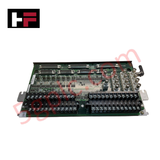
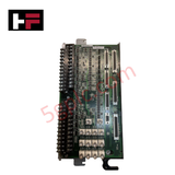
Configured for high-frequency signal acquisition in Mark VI control platforms, the GE IS200TVIBH2B (IS200TVIBH2B Vibration Terminal Board) provides direct physical/electrical execution of transducer interfacing for mechanical monitoring.
Hardware Specifications
| Parameter | Specification |
|---|---|
| Model | IS200TVIBH2B |
| Brand | General Electric |
| Origin | USA |
| Weight | Not specified |
| Dimensions | 13 in x 7 in |
| Operating Temp | 0 to 60 deg C |
| Power Consumption | Not specified |
| Channel Count | 13 |
| Compatibility | Bently Nevada Proximitor, Seismic, Accelerometer, Velomitor |
Eddy-Current Probe Scaling and Signal Processing
The IS200TVIBH2B serves as the interface between turbine-mounted transducers and the VVIB processing boards. It supports multiple probe technologies, including Proximitors and seismic sensors. To ensure accurate rotor dynamics analysis, the board facilitates consistent signal path impedance, allowing for precise eddy-current probe scaling. This configuration ensures that gap voltage validation remains within the operational -10 VDC target range. The terminal board maintains signal integrity to enable effective cross-talk suppression between the 13 channels before the signals are routed to the VVIB boards for analog-to-digital conversion and subsequent transmission via the VME bus to the central controller.
Frequently Asked Questions
Q: Does the IS200TVIBH2B support hot-swapping?
A: Hot-swapping the terminal board is restricted due to the direct electrical connection with active vibration probes. Isolation of the VVIB power supply is required prior to removal to prevent transient voltage spikes on the transducer loops.
Q: How are TMR (Triple Modular Redundancy) configurations managed?
A: In TMR mode, the terminal board distributes signals to three concurrent VVIB processing units. The system controller performs voting logic on the digitized signals to reject outlier data caused by individual channel faults.
Field Installation Guidelines
- Mounting: Secure the board into the designated Mark VI rack slot. Verify that the rear-plane connectors are fully seated to maintain ground continuity, which is required for low-noise sensor signal acquisition.
- Shielding: All transducer cabling must use high-quality shielded twisted-pair conductors. Terminate shields at the cabinet-level grounding bar using 360-degree clamps to minimize susceptibility to electromagnetic interference.
- Probe Wiring: Ensure that the wiring polarity matches the transducer requirements (e.g., Bently Nevada interface standards). Improper wiring can invert signal polarity, leading to incorrect rotor position or vibration amplitude data.
- Thermal Management: Maintain clear airflow paths in the Mark VI cabinet. The 0 to 60 deg C operating range must be strictly observed to prevent thermal drift in the analog input circuits, which would invalidate rotor dynamic measurements.
Additional Information
- 100% Genuine Parts: All products are original and authentic, ensuring reliable industrial performance.
- 30-Day Refund Guarantee: Return any in-stock item within 30 days in original, unopened packaging for a full refund (excluding shipping and fees).
- 12-Month Warranty: Covers defects in materials or workmanship; excludes misuse, normal wear, or unauthorized modifications.
- Worldwide Shipping: We ship via USPS, UPS, FedEx, and DHL. Delivery times vary by country and may be subject to customs or import fees.
- Support & Contact: Technical and warranty assistance is available anytime. Contact us here: Contact.
- Purchase Guidance: Check product specifications and compatibility carefully before ordering to ensure proper application.


Tech & Buying Guide

Why 24V DC Power Supplies Standardize Modern Industrial Automation
Industrial control cabinets worldwide rely on 24V DC as the universal power standard for field instrumentation, sensors, and controllers. Walk into any manufacturing plant, and you will find PLCs, human-machine interfaces (HMIs), and smart actuators running on extra-low voltage DC. Standardizing on 24V DC enhances operational safety, lowers cabinet footprint, and maintains steady control performance across factory networks.

Essential Motion Control Commands: A Practical Guide for Engineers
Automation engineers often rely on precise position and speed control to drive modern factory machinery. Modern industrial systems, such as Programmable Logic Controllers (PLCs) and Distributed Control Systems (DCS), depend heavily on standardized motion instructions. Mastering these commands ensures operational safety, protects mechanical components, and optimizes cycle times across production lines.

Mastering Modern Industrial Joystick Controls in Heavy Automation
Industrial joysticks play a pivotal role in human-machine interaction across heavy material handling and mobile hydraulics. These tactile controllers translate complex operator movements into precise electrical signals for PLCs, motion controllers, and DCS networks. Consequently, selecting and installing the right joystick architecture ensures operator safety, reduces fatigue, and optimizes equipment performance.