










Product Details
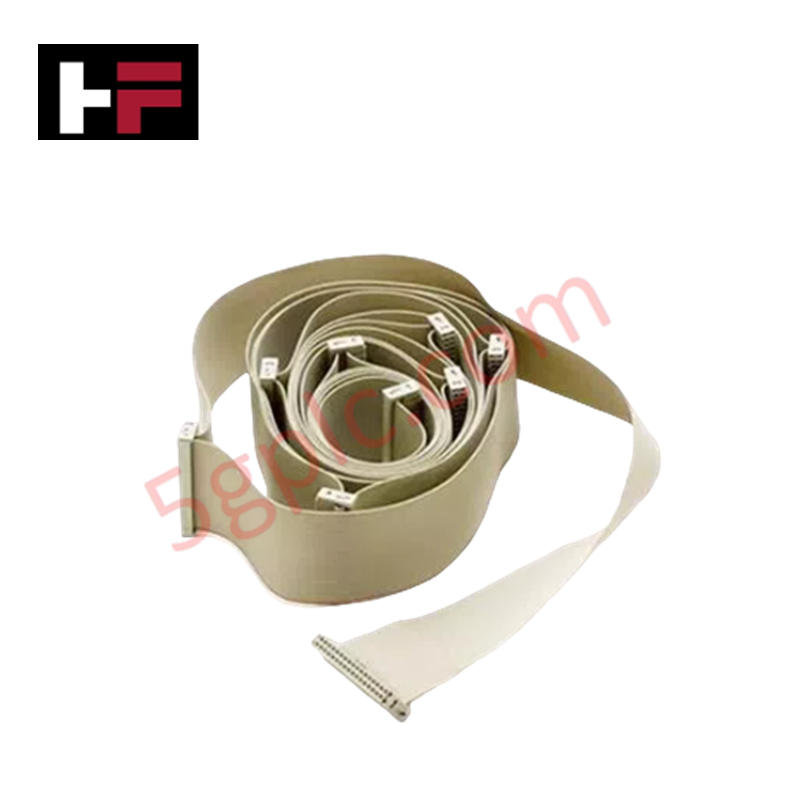
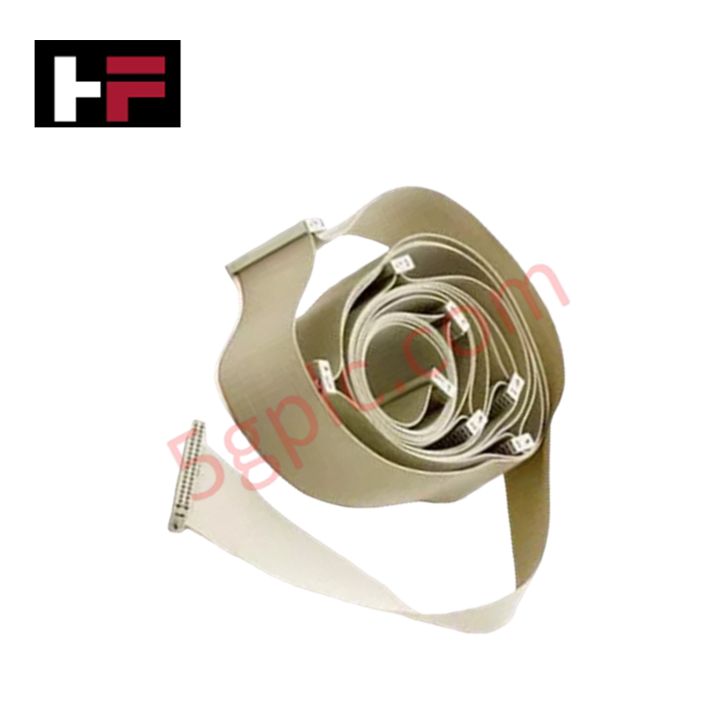
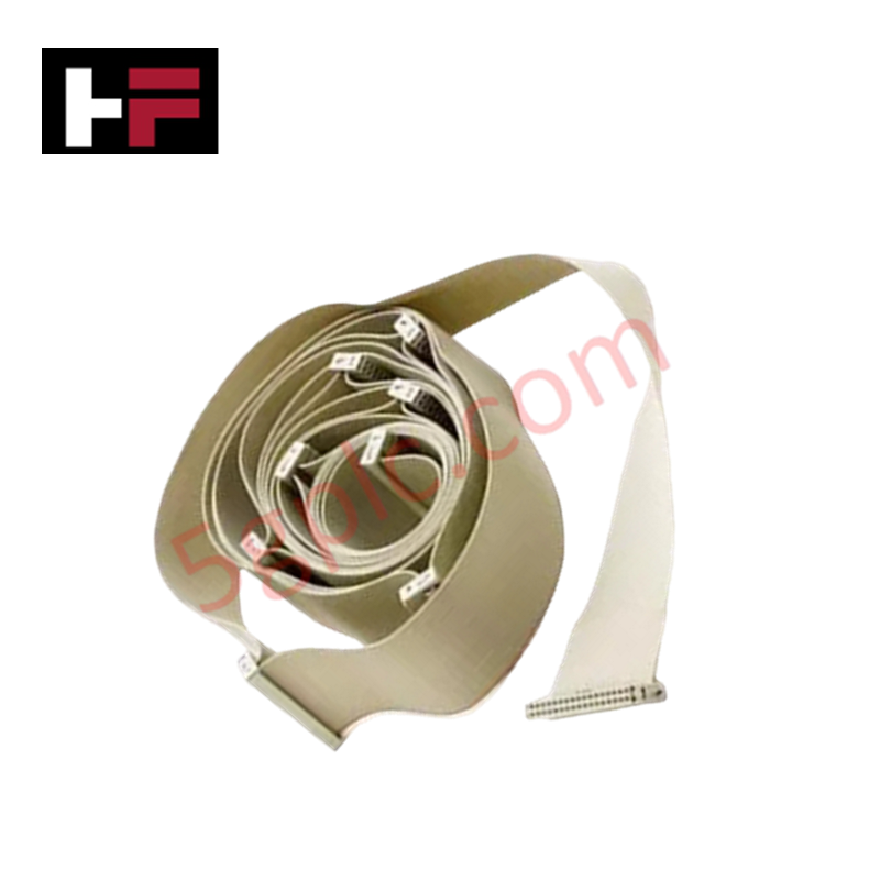
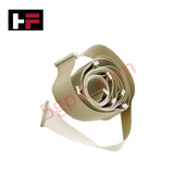
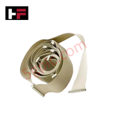
Configured for high-speed inter-chassis signal routing in Honeywell Safety Manager platforms, the Honeywell FS-IOBUS-CPIO (FS-IOBUS-CPIO I/O Bus Cable) provides direct physical/electrical execution. It links controller chassis to remote I/O racks using dual 34-pole female latch connectors.
Hardware Specifications
| Parameter | Specification |
|---|---|
| Model | FS-IOBUS-CPIO |
| Brand | Honeywell |
| Origin | USA |
| Weight | 0.31 kg (net weight) / 2.5 kg (shipping weight) |
| Dimensions | Chassis-to-chassis bus cable dimensions |
| Operating Temp | -20 to +60 deg C |
| Power Consumption | Passive interconnect assembly (Zero internal power draw) |
| Connectors | 34-pole latch female connectors |
| Approvals | UL, CSA |
| System Compatibility | Honeywell Safety Manager / Experion PKS |
Process Control & DCS Signal Interconnection Characteristics
The FS-IOBUS-CPIO cable assembly provides channel-to-channel isolation along backplane communication channels to block common-mode noise across cabinet enclosures. The high-density 34-pole conductor matrix preserves low-latency differential signal routing between central controller modules and target I/O chassis. This interface maintains deterministic throughput for field bus telemetry and 4-20 mA HART loop protocol device communication.
Frequently Asked Questions
Q: What physical latching mechanism is used to hold the FS-IOBUS-CPIO cable in place?
A: The assembly incorporates dual 34-pole female connectors featuring integrated mechanical latches to prevent accidental disconnection during panel vibration or cabinet service.
Q: Can the FS-IOBUS-CPIO bus cable be disconnected while the controller backplane is under power?
A: Hot-unplugging is permitted only within parallel redundant bus configurations; removing a single active I/O bus cable interrupts logic solver polling to all downstream I/O modules on that branch.
Field Installation Guidelines
- Connector Alignment and Latching: Align the 34-pole female socket squarely with the male pin header on the controller or I/O chassis. Press firmly until the side locking latches click fully into place.
- Bend Radius Limits: Lay the cable inside dedicated wire raceways. Maintain a minimum static bend radius of 50 mm to prevent physical stress on internal conductor crimps and shielding.
- Shield Grounding: Verify that internal braid drain wires are grounded through the header backshell to the master cabinet earth bar to mitigate high-frequency interference.
- Wiring Segregation: Maintain at least 30 cm clearance between the I/O bus cable assembly and AC power lines or heavy inductive load switching devices.
Additional Information
- 100% Genuine Parts: All products are original and authentic, ensuring reliable industrial performance.
- 30-Day Refund Guarantee: Return any in-stock item within 30 days in original, unopened packaging for a full refund (excluding shipping and fees).
- 12-Month Warranty: Covers defects in materials or workmanship; excludes misuse, normal wear, or unauthorized modifications.
- Worldwide Shipping: We ship via USPS, UPS, FedEx, and DHL. Delivery times vary by country and may be subject to customs or import fees.
- Support & Contact: Technical and warranty assistance is available anytime. Contact us here: Contact.
- Purchase Guidance: Check product specifications and compatibility carefully before ordering to ensure proper application.




Tech & Buying Guide

Master Acceptance Testing: Understanding FAT and SAT in Industrial Control Systems
Factory Acceptance Testing (FAT) and Site Acceptance Testing (SAT) serve as critical quality assurance gateways in complex industrial control systems. Both procedures verify that programmable logic controllers (PLCs), distributed control systems (DCS), and associated field devices meet strict functional specifications. However, executing these tests effectively requires clear delineation between off-site staging and final field commissioning.

Industrial Networking Essentials: Demystifying Hubs, Switches, and Routers in Control Systems
Industrial automation relies heavily on robust networking infrastructure to connect programmable logic controllers (PLCs), distributed control systems (DCS), and human-machine interfaces (HMIs). Modern factory automation environments generate vast amounts of real-time operational data across deterministic networks. Understanding the structural differences between hubs, switches, and routers ensures optimal traffic segmentation, minimizes latency, and maintains high network availability.

Safety Relays in Industrial Automation: Fundamentals, Design Standards, and Fail-Safe Architecture
Safety relays form the bedrock of functional safety in modern factory automation, preventing catastrophic equipment failure and protecting plant personnel. While standard electromechanical relays handle basic load switching, they lack the redundant diagnostics required for high-risk industrial environments. Modern industrial automation platforms—including programmable logic controllers (PLCs) and distributed control systems (DCS)—rely on specialized safety relays to monitor field devices and isolate hazards instantly.