


Product Details
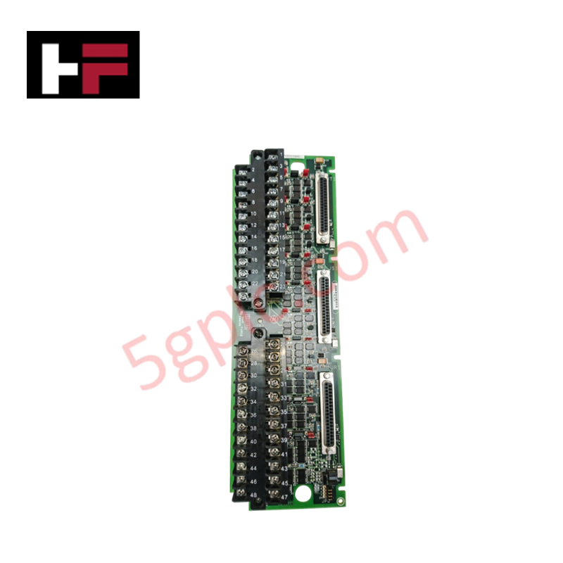
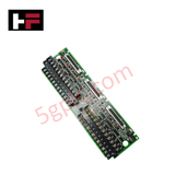
Configured for analog signal processing in Mark VIe safety-integrated systems, the GE IS200TBAIS1C (IS200TBAIS1C Analog Input/Output Terminal Board) provides direct physical/electrical execution. This terminal board supports both simplex and triple modular redundancy (TMR) configurations, managing thermocouple, current loop, and voltage signals while facilitating precise current regulation through integrated shunt measurement circuitry.
Hardware Specifications
| Parameter | Specification |
|---|---|
| Model | IS200TBAIS1C |
| Brand | General Electric |
| Origin | USA |
| Weight | Not specified |
| Dimensions | Standard Mark VIe terminal board form factor |
| Operating Temp | Industrial standard range |
| Power Consumption | Dependent on connected I/O loops |
| Connection Type | 3 x DC-37 pin I/O processor connectors |
Triple Modular Redundancy (TMR) and Fail-Safe Execution
The IS200TBAIS1C is engineered for safety-certified applications within the Mark VIeS SIS environment. In TMR 2oo3 configurations, the terminal board enables signal fanning, where inputs are distributed across the R, S, and T control channels. The board utilizes an integrated measuring shunt to aggregate current from triple-connected output drivers, providing a composite signal to the I/O processors for accurate setpoint regulation. The design enforces fail-safe state execution, ensuring that in the event of an I/O processor discrepancy, the voter logic maintains the safety-critical state. Note that the 200 mA output option is restricted in YAIC-based SIS applications to ensure compliance with certified safety parameters.
Frequently Asked Questions
Q: Is the IS200TBAIS1C compatible with simplex application topologies?
A: Yes. The board utilizes a dedicated single connector (R1) for simplex applications, while all three DC-37 pin connectors are utilized for TMR configurations to support redundant processing.
Q: How is output current handled in TMR mode?
A: In TMR mode, the terminal board aggregates the currents from the three connected output drivers. An onboard measuring shunt calculates the total current, which is then fed back to the I/O processors to ensure precise regulation to the commanded setpoint.
Field Installation Guidelines
- Interface Cabling: Connect I/O processors to the three DC-37 pin ports. For simplex setups, ensure the R1 port is utilized. For TMR, ensure cabling from all three processors (R, S, T) is verified against the system wiring schematic to prevent signal phase or addressing errors.
- Shielding and Grounding: To maintain safety certification integrity, land all cable shields on the designated terminal board grounding points. Minimize path impedance to the system common earth ground to avoid noise-induced errors in analog measurement circuits.
- Terminal Block Torque: Apply proper torque to the barrier-style terminal blocks when landing field wiring. Loose connections can introduce resistive fluctuations, causing instability in current-loop feedback signals.
- Environmental Considerations: Ensure the installation environment remains within rated limits. Avoid proximity to high-frequency power switching equipment to prevent EMI coupling into sensitive low-level analog inputs.
Additional Information
- 100% Genuine Parts: All products are original and authentic, ensuring reliable industrial performance.
- 30-Day Refund Guarantee: Return any in-stock item within 30 days in original, unopened packaging for a full refund (excluding shipping and fees).
- 12-Month Warranty: Covers defects in materials or workmanship; excludes misuse, normal wear, or unauthorized modifications.
- Worldwide Shipping: We ship via USPS, UPS, FedEx, and DHL. Delivery times vary by country and may be subject to customs or import fees.
- Support & Contact: Technical and warranty assistance is available anytime. Contact us here: Contact.
- Purchase Guidance: Check product specifications and compatibility carefully before ordering to ensure proper application.


Tech & Buying Guide

Why 24V DC Power Supplies Standardize Modern Industrial Automation
Industrial control cabinets worldwide rely on 24V DC as the universal power standard for field instrumentation, sensors, and controllers. Walk into any manufacturing plant, and you will find PLCs, human-machine interfaces (HMIs), and smart actuators running on extra-low voltage DC. Standardizing on 24V DC enhances operational safety, lowers cabinet footprint, and maintains steady control performance across factory networks.

Essential Motion Control Commands: A Practical Guide for Engineers
Automation engineers often rely on precise position and speed control to drive modern factory machinery. Modern industrial systems, such as Programmable Logic Controllers (PLCs) and Distributed Control Systems (DCS), depend heavily on standardized motion instructions. Mastering these commands ensures operational safety, protects mechanical components, and optimizes cycle times across production lines.

Mastering Modern Industrial Joystick Controls in Heavy Automation
Industrial joysticks play a pivotal role in human-machine interaction across heavy material handling and mobile hydraulics. These tactile controllers translate complex operator movements into precise electrical signals for PLCs, motion controllers, and DCS networks. Consequently, selecting and installing the right joystick architecture ensures operator safety, reduces fatigue, and optimizes equipment performance.