


Product Details
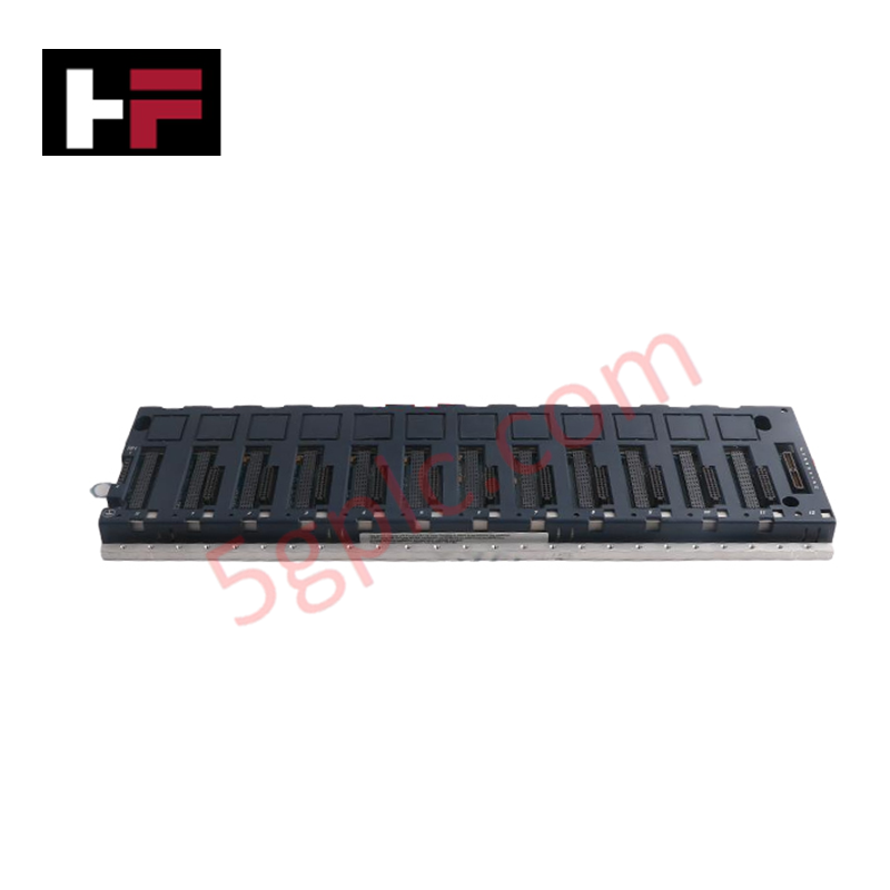
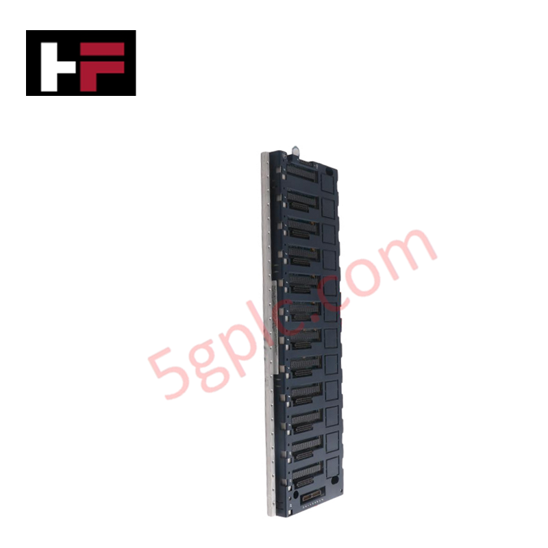
Configured for contact signal management in EX2100 Excitation Control System platforms, the GE IS200ECTBG2A (IS200ECTBG2A Exciter Contact Terminal Board) provides direct physical/electrical execution of auxiliary contact monitoring and relay trip control.
Hardware Specifications
| Parameter | Specification |
|---|---|
| Model | IS200ECTBG2A |
| Brand | General Electric |
| Origin | USA |
| Weight | 3.25 lbs |
| Auxiliary Inputs | 6 x Contact Inputs (including 52G, 86G) |
| Relay Outputs | 2 x Trip Outputs, 4 x Form-C Relay Outputs |
| Control Voltage | Isolated +70 VDC (sourced from EPSM module) |
Backplane Bus Communication Velocity and Firmware Compatibility
The IS200ECTBG2A functions as a managed I/O terminal board within the EX2100 architecture. It relies on the EMIO (Exciter Main I/O) board to collect contact state data and relay control logic. The processed I/O states are transmitted as logic-level gate pulse signals across the internal backplane to the ESEL board. This deterministic communication loop ensures that the trip contact outputs are processed within the defined scan time of the excitation control system. Firmare compatibility is managed at the system level via the EMIO interface, ensuring that the terminal board inputs remain mapped to the correct logical addresses in the ESEL control processor.
Frequently Asked Questions
Q: Can the IS200ECTBG2A be used in redundant system configurations?
A: No. The G2 version of this board is specifically engineered for Simplex Mode. Redundant system architectures require the G1 board variant to support necessary dual-mode logic and signal voting.
Q: How is the contact wetting voltage managed?
A: The board receives an isolated +70 VDC supply directly from the associated EPSM module. This voltage is applied to the auxiliary contact inputs for monitoring purposes. Ensure no external voltage sources are applied to these input terminals to prevent damage to the isolation circuitry.
Field Installation Guidelines
- Mounting: The board must be mounted in a standard EX2100 cabinet slot. Ensure all captive fasteners are tightened to maintain electrical continuity between the board chassis and the cabinet ground plane.
- Wiring: Auxiliary inputs (such as 52G and 86G) must be wired using shielded, twisted-pair cabling. Terminate cable shields at the designated cabinet grounding bar to mitigate electromagnetic interference that could cause erroneous contact state changes.
- Power Isolation: Prior to installation or cable termination, verify that the +70 VDC supply from the EPSM module is disconnected. Use a digital multimeter to confirm zero potential at the terminals before proceeding with wiring.
- Logic Verification: After installation, verify the mapping of the 6 auxiliary inputs and 6 total relay outputs within the EX2100 system configuration software to ensure the logic-level gate pulses are correctly interpreted by the ESEL board.
Additional Information
- 100% Genuine Parts: All products are original and authentic, ensuring reliable industrial performance.
- 30-Day Refund Guarantee: Return any in-stock item within 30 days in original, unopened packaging for a full refund (excluding shipping and fees).
- 12-Month Warranty: Covers defects in materials or workmanship; excludes misuse, normal wear, or unauthorized modifications.
- Worldwide Shipping: We ship via USPS, UPS, FedEx, and DHL. Delivery times vary by country and may be subject to customs or import fees.
- Support & Contact: Technical and warranty assistance is available anytime. Contact us here: Contact.
- Purchase Guidance: Check product specifications and compatibility carefully before ordering to ensure proper application.


Tech & Buying Guide

Why 24V DC Power Supplies Standardize Modern Industrial Automation
Industrial control cabinets worldwide rely on 24V DC as the universal power standard for field instrumentation, sensors, and controllers. Walk into any manufacturing plant, and you will find PLCs, human-machine interfaces (HMIs), and smart actuators running on extra-low voltage DC. Standardizing on 24V DC enhances operational safety, lowers cabinet footprint, and maintains steady control performance across factory networks.

Essential Motion Control Commands: A Practical Guide for Engineers
Automation engineers often rely on precise position and speed control to drive modern factory machinery. Modern industrial systems, such as Programmable Logic Controllers (PLCs) and Distributed Control Systems (DCS), depend heavily on standardized motion instructions. Mastering these commands ensures operational safety, protects mechanical components, and optimizes cycle times across production lines.

Mastering Modern Industrial Joystick Controls in Heavy Automation
Industrial joysticks play a pivotal role in human-machine interaction across heavy material handling and mobile hydraulics. These tactile controllers translate complex operator movements into precise electrical signals for PLCs, motion controllers, and DCS networks. Consequently, selecting and installing the right joystick architecture ensures operator safety, reduces fatigue, and optimizes equipment performance.