








Product Details
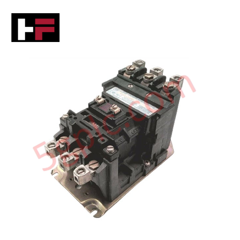
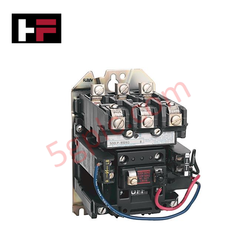
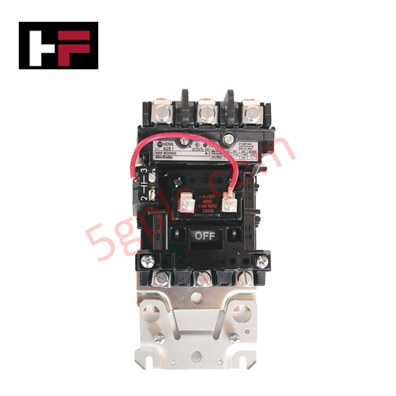
Configured for power distribution control in industrial load circuits, the Allen-Bradley 500FL-COD93 (500FL-COD93 Contactor) provides direct physical/electrical execution of circuit switching via a three-pole, top-wired feed-thru architecture.
Hardware Specifications
| Parameter | Specification |
|---|---|
| Model | 500FL-COD93 |
| Brand | Allen-Bradley |
| Origin | USA |
| Weight | 0.45 kg |
| NEMA Size | 2 |
| Coil Voltage | 110/120 VAC, 50/60 Hz |
| Poles | 3 Main Poles |
ProSoft / DIN-Rail Mounting Stability and Electrical Protection
The 500FL-COD93 contactor assembly is designed for installation within open-type enclosures to ensure adequate thermal dissipation. The top-wired feed-thru configuration facilitates streamlined vertical cabling, reducing mechanical stress on the primary terminals. Users must ensure that the surge voltage protection limits of the control circuit are respected when triggering the 120 VAC coil to prevent back-EMF damage to solid-state control logic. Proper mechanical mounting stability on the backplane is mandatory to prevent vibration-induced contact bounce, which can lead to premature wear of the main power poles.
Frequently Asked Questions
Q: Is this contactor suitable for applications involving frequent cycling?
A: The contactor is rated for standard industrial duty. For applications requiring extremely high cycle rates, the mechanical fatigue life of the contact structure and spring return assembly must be factored into the preventive maintenance schedule.
Q: Can the 120 VAC coil be driven by a 24 VDC control signal?
A: No. The coil is specifically rated for 110/120 VAC operation at 50/60 Hz. Driving the coil with 24 VDC will result in failure to engage the contactor, while exceeding the voltage rating will result in immediate coil burnout. An intermediate interposing relay is required to bridge the voltage differential.
Field Installation Guidelines
- Inspect the contactor housing and main poles for debris or shipping damage prior to panel installation.
- Secure the open-type contactor to the mounting surface using specified hardware, ensuring the device is level to maintain proper mechanical orientation for the internal armature.
- Terminate primary power lines to the top-side feed-thru terminals; ensure all connections are torqued to the manufacturer’s specification to prevent localized heating.
- Verify that the control circuit wire gauge is sufficient for the 120 VAC coil current draw and is routed away from high-voltage power lines.
- Confirm that the contactor moves freely when manually depressed; ensure no wiring binds or interferes with the armature mechanism.
- Energize the coil circuit to perform a continuity test across the main power poles, verifying a positive and audible "snap" during engagement.
Additional Information
- 100% Genuine Parts: All products are original and authentic, ensuring reliable industrial performance.
- 30-Day Refund Guarantee: Return any in-stock item within 30 days in original, unopened packaging for a full refund (excluding shipping and fees).
- 12-Month Warranty: Covers defects in materials or workmanship; excludes misuse, normal wear, or unauthorized modifications.
- Worldwide Shipping: We ship via USPS, UPS, FedEx, and DHL. Delivery times vary by country and may be subject to customs or import fees.
- Support & Contact: Technical and warranty assistance is available anytime. Contact us here: Contact.
- Purchase Guidance: Check product specifications and compatibility carefully before ordering to ensure proper application.
Tech & Buying Guide

Site Acceptance Testing (SAT) for PLC Control Systems: An Engineering Execution Guide
The Site Acceptance Test (SAT) represents the definitive handover stage in industrial automation projects. While the Factory Acceptance Test confirms cabinet hardware assembly off-site, the SAT validates real-world performance under live site conditions. Consequently, a structured execution strategy prevents equipment damage and guarantees seamless integration into plant operations.

Mastering the Factory Acceptance Test (FAT) for PLC Control Panels: An Expert Guide
The Factory Acceptance Test (FAT) is a vital milestone in industrial automation that ensures custom PLC panels meet exact design specifications before dispatch. This guide outlines the step-by-step FAT procedure and key industry best practices to prevent costly site delays and ensure long-term operational success.

Redundant Automation Systems: Ensuring Continuous Uptime in Critical Control Infrastructure
System reliability directly determines operational profitability across high stakes process industries. Modern industrial automation platforms must eliminate single points of failure to prevent catastrophic shutdowns. Deploying fault tolerant architecture safeguards complex facilities against unexpected hardware glitches, network disruptions, and maintenance outages.