


Product Details
Product Overview
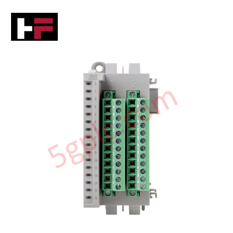
The Allen-Bradley 2085-OB16 operates as a high-density digital output expansion module within the Micro850 and Micro870 programmable logic controller (PLC) ecosystems. This hardware component expands the base controller's switching capacity by providing 16 discrete sourcing output channels.
The module acts as a direct command interface, switching DC power lines to drive field assets like pneumatic solenoids, pilot indicator lights, control relays, and small DC motor starters. We supply this automation hardware exclusively as a 100% brand new, original factory-sealed unit, which guarantees zero previous thermal stress, virgin silicon transistor pathways, and unblemished backplane connector pins.
Technical Specifications
The table below maps the electrical profiles, channel densities, and physical parameters of the 2085-OB16 sourcing output module:
| Parameter | Performance & Industrial Control Rating |
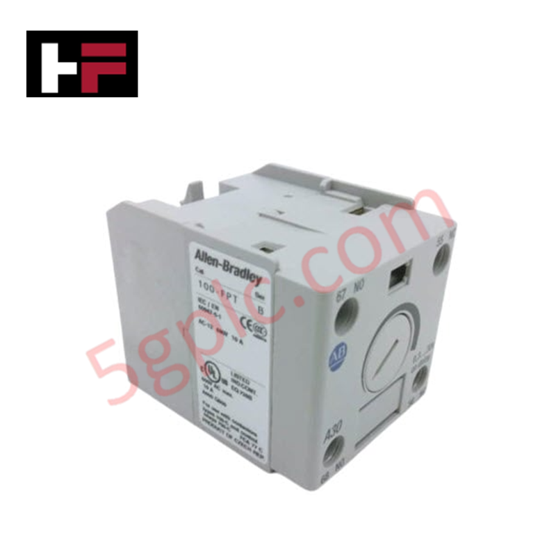
| Manufacturer | Allen-Bradley / Rockwell Automation |
| Part Number | 2085-OB16 |
| Controller Compatibility | Micro850 / Micro870 PLC Systems |
| Output Type | Solid-State Digital Transistor |
| Output Configuration | Sourcing (Source Type Circuitry) |
| Total Number of Outputs | 16 Channels |
| Operating Voltage Range | 10V to 30V DC |
| Nominal Supply Voltages | 12V DC / 24V DC |
| Continuous Current Per Channel | 0.5 Amps Maximum |
| Continuous Current Per Module | 8.0 Amps Maximum |
| Status Indicators | 16 Amber Channel LEDs / 1 Green Power LED |
| Mounting Mechanism | DIN Rail or Panel Mount Configuration |
Engineering Advantages
-
Maximizes Control Density in Tight Enclosures: The compact form factor packs 16 independent solid-state outputs into a slim module housing. This layout minimizes the physical footprint on the DIN rail, letting panel builders pack higher I/O counts into shallow terminal junction boxes or congested machinery control panels.
-
Eliminates Contact Mechanical Wear via Solid-State Sourcing: Solid-state transistors handle all switching operations instead of mechanical copper contacts. This sourcing design eliminates contact arcing, welding, and structural fatigue, delivering millions of rapid switching cycles without degradation when driving reactive inductive loads like solenoid valves.
-
Accelerates Field Diagnosis via Channel-Specific LEDs: A dedicated bank of 16 amber status LEDs lines the front face of the housing. These indicators mirror the exact logical state of the internal transistors, allowing maintenance technicians to verify output status at a glance and isolate downstream wiring faults without hooking up a programming laptop.
FAQs
-
What is the operational difference between this sourcing module and a sinking output module?
The 2085-OB16 uses a sourcing configuration, meaning each output channel supplies positive (+VDC) power directly from the module terminal to the field device when activated. The field device must connect back to the common negative (0V DC) return line. Sinking modules, by contrast, pull the load down to the negative return line, requiring a constant positive feed at the field device.
-
Can this module supply power directly from the PLC backplane to drive heavy field solenoids?
No. The internal PLC backplane only provides low-power logic voltages to run the module's microchips. Technicians must connect an external, independent 12V or 24V DC power supply to the dedicated field power terminals on the removable front connector block to energize the 16 output circuits and drive connected field loads.
-
What precautions prevent electrical back-EMF damage when switching inductive loads?
While the solid-state design handles standard currents, inductive devices like large relay coils or magnetic clutches generate high-voltage reverse EMF spikes when they turn off. To prevent gradual transistor degradation, technicians should wire a flyback diode in parallel across DC inductive loads to safely suppress voltage surges before they travel back to the module.
Additional Information
- 100% Genuine Parts: All products are original and authentic, ensuring reliable industrial performance.
- 30-Day Refund Guarantee: Return any in-stock item within 30 days in original, unopened packaging for a full refund (excluding shipping and fees).
- 12-Month Warranty: Covers defects in materials or workmanship; excludes misuse, normal wear, or unauthorized modifications.
- Worldwide Shipping: We ship via USPS, UPS, FedEx, and DHL. Delivery times vary by country and may be subject to customs or import fees.
- Support & Contact: Technical and warranty assistance is available anytime. Contact us here: Contact.
- Purchase Guidance: Check product specifications and compatibility carefully before ordering to ensure proper application.


Tech & Buying Guide

Site Acceptance Testing (SAT) for PLC Control Systems: An Engineering Execution Guide
The Site Acceptance Test (SAT) represents the definitive handover stage in industrial automation projects. While the Factory Acceptance Test confirms cabinet hardware assembly off-site, the SAT validates real-world performance under live site conditions. Consequently, a structured execution strategy prevents equipment damage and guarantees seamless integration into plant operations.

Mastering the Factory Acceptance Test (FAT) for PLC Control Panels: An Expert Guide
The Factory Acceptance Test (FAT) is a vital milestone in industrial automation that ensures custom PLC panels meet exact design specifications before dispatch. This guide outlines the step-by-step FAT procedure and key industry best practices to prevent costly site delays and ensure long-term operational success.

Redundant Automation Systems: Ensuring Continuous Uptime in Critical Control Infrastructure
System reliability directly determines operational profitability across high stakes process industries. Modern industrial automation platforms must eliminate single points of failure to prevent catastrophic shutdowns. Deploying fault tolerant architecture safeguards complex facilities against unexpected hardware glitches, network disruptions, and maintenance outages.