


Product Details
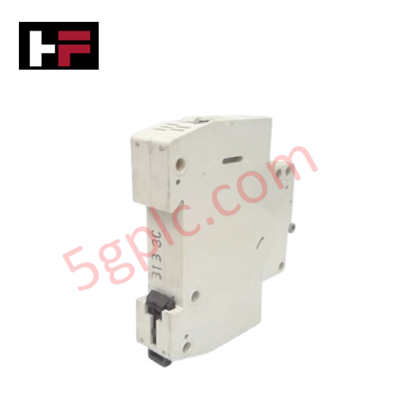
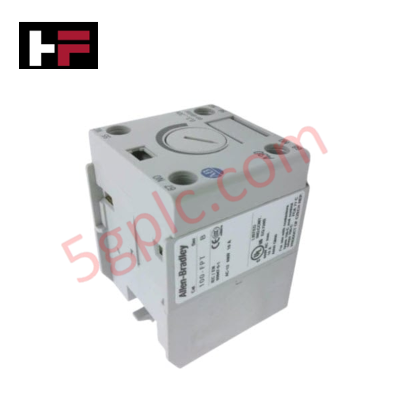
Configured for overcurrent protection in control circuit branches, the Allen-Bradley 1492-SP1C030 (1492-SP1C030 Circuit Breaker) provides direct physical/electrical execution of single-pole circuit interruption under overload and short-circuit conditions.
Hardware Specifications
| Parameter | Specification |
|---|---|
| Model | 1492-SP1C030 |
| Brand | Allen-Bradley |
| Origin | USA |
| Weight | 0.11 kg |
| Dimensions | Not Specified |
| Operating Temp | Not Specified |
| Power Consumption | Not Applicable |
| Current Rating | 3 A |
| Voltage Rating | 240/415 VAC |
| Interrupt Rating | 10 kA |
Profinet / EtherNet/IP Deterministic Networks
The 1492-SP1C030 employs a C-curve trip characteristic, providing a targeted response to moderate inrush currents while maintaining sensitivity to sustained overloads. In modular automation architectures, effective I/O density scaling relies on coordinating these protective devices with upstream distribution blocks to prevent nuisance tripping across deterministic communication segments. This component does not interface directly with fieldbus networks; however, the mechanical trip mechanism is engineered to ensure high-speed disconnection during fault transients, thereby protecting downstream I/O modules and backplane bus segments from severe current surges.
Frequently Asked Questions
Q: Does this circuit breaker support field-installable accessories?
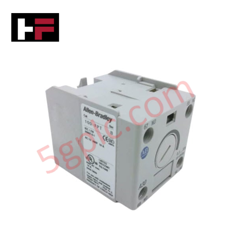
A: The Bulletin 1492-SP series supports the installation of various accessories, including auxiliary contacts and signal switches, which mount to the side of the breaker to provide status indication to the PLC.
Q: Is this device intended for direct motor protection?
A: No. This device is a supplementary protector and is rated for control circuit protection. It is not designed to serve as a motor branch circuit protector or to provide the thermal overload protection required for motor drives.
Field Installation Guidelines
- Install the breaker onto a standard 35 mm DIN rail; ensure the base latch is fully secured to prevent vibration-induced movement.
- Connect the line-side power supply to the top terminals and load-side wiring to the bottom terminals, verifying consistent wire gauge application.
- Apply correct tightening torque to terminal screws to maintain low-impedance electrical contact and prevent thermal degradation of the connection point.
- Separate secondary control wiring from primary power cabling or variable frequency drive (VFD) output lines to mitigate electromagnetic noise coupling.
- Ensure the surrounding enclosure provides adequate ingress protection and that the device remains clear of conductive dust or debris.
- Verify circuit operation by measuring voltage at the load-side terminals with the device in the "ON" position to confirm functional continuity.
Additional Information
- 100% Genuine Parts: All products are original and authentic, ensuring reliable industrial performance.
- 30-Day Refund Guarantee: Return any in-stock item within 30 days in original, unopened packaging for a full refund (excluding shipping and fees).
- 12-Month Warranty: Covers defects in materials or workmanship; excludes misuse, normal wear, or unauthorized modifications.
- Worldwide Shipping: We ship via USPS, UPS, FedEx, and DHL. Delivery times vary by country and may be subject to customs or import fees.
- Support & Contact: Technical and warranty assistance is available anytime. Contact us here: Contact.
- Purchase Guidance: Check product specifications and compatibility carefully before ordering to ensure proper application.


Tech & Buying Guide

Navigating Industrial Automation Failures: Types, Causes, and Mitigation Strategies
Modern manufacturing relies heavily on automated control systems to maximize throughput and maintain product quality. However, unplanned downtime in industrial automation can cost facility operators thousands of dollars per hour. Understanding how programmable logic controllers (PLCs), distributed control systems (DCS), and field instrumentation fail empowers engineering teams to implement robust preventive maintenance strategies.

Essential Motion Control Commands: A Practical Guide for Engineers
Automation engineers often rely on precise position and speed control to drive modern factory machinery. Modern industrial systems, such as Programmable Logic Controllers (PLCs) and Distributed Control Systems (DCS), depend heavily on standardized motion instructions. Mastering these commands ensures operational safety, protects mechanical components, and optimizes cycle times across production lines.

The Role of Intrinsic Safety Barriers in PLC and DCS Architectures
Implementing robust protection in hazardous industrial environments represents a fundamental safety requirement in factory automation. Process facilities often handle volatile gases, dusts, and chemical agents that pose significant combustion risks. Consequently, control system engineers must deploy energy-limiting interfaces to isolate safe-area control cabinets from hazardous-area field instrumentation. This article examines the function, selection, and electrical principles of intrinsic safety barriers within modern PLC and DCS networks.