


Product Details
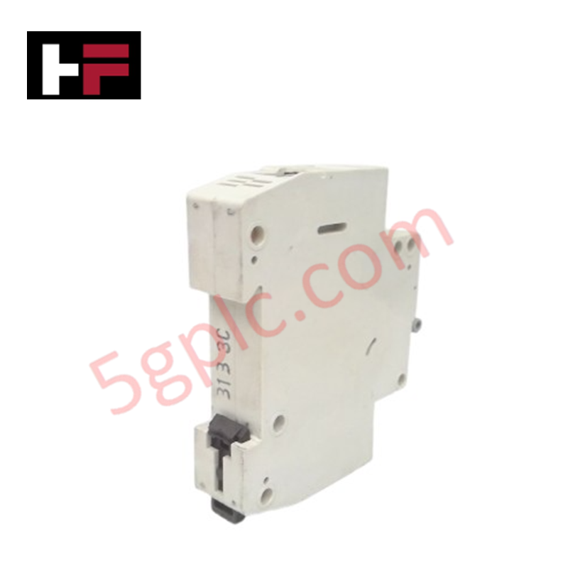
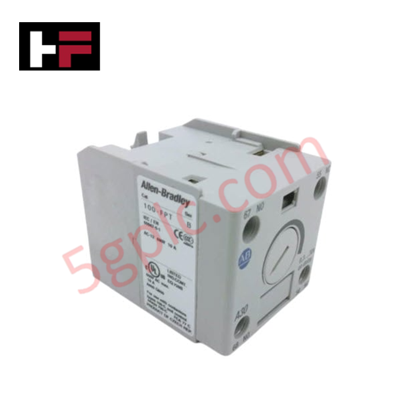
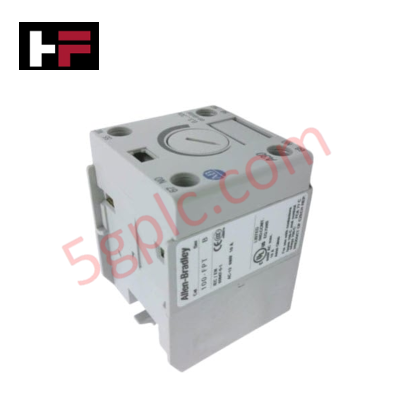
Configured for overcurrent protection in control circuit branches, the Allen-Bradley 1492-SP1C020 (1492-SP1C020 Supplementary Protector) provides direct physical/electrical execution of single-pole circuit interruption under overload and short-circuit conditions.
Hardware Specifications
| Parameter | Specification |
|---|---|
| Model | 1492-SP1C020 |
| Brand | Allen-Bradley |
| Origin | USA |
| Weight | 0.11 kg |
| Power Consumption | Not Applicable |
| Current Rating | 2 A |
| Poles | 1 Pole |
| Voltage Rating | 277 VAC |
Profinet / EtherNet/IP Deterministic Networks
The 1492-SP1C020 utilizes a thermal-magnetic mechanism to achieve deterministic interruption of branch circuits. In high-density control architectures, this protector enables precise I/O density scaling by isolating individual load segments, which prevents localized faults from compromising the stability of broader Profinet or EtherNet/IP deterministic networks. While this hardware lacks internal network communications, its electrical profile is calibrated for integration within control systems where firmware flash compatibility of adjacent controllers is standard. Users should perform fault current analysis to ensure that branch-level protection coordinates with upstream distribution hardware.
Frequently Asked Questions
Q: Is this device suitable for motor starting applications?
A: No. As a supplementary protector, this unit is designed for control circuit protection and lacks the specific thermal-magnetic characteristics required for motor branch circuit protection under standard industrial codes.
Q: Can this 1-pole protector be used in 277 VAC single-phase circuits?
A: Yes, provided the circuit configuration is compatible with a single-pole interruption mechanism and the fault current does not exceed the component's interrupt rating.
Field Installation Guidelines
- Mount the unit onto a standard 35 mm DIN rail; ensure the base latching mechanism is fully engaged to maintain mechanical stability during panel vibration.
- Terminate line-side power connections at the upper terminals and load-side conductors at the lower terminals.
- Observe correct wire stripping lengths to ensure full engagement within the clamp terminals without exposing bare copper beyond the terminal housing.
- Separate the protected control circuit wiring from high-voltage power lines or VFD output cabling to minimize induced electromagnetic interference.
- Verify circuit continuity with a multimeter in the de-energized state before applying power.
- Periodically verify terminal torque to maintain low-impedance electrical contact, preventing thermal degradation of the connection point.
Additional Information
- 100% Genuine Parts: All products are original and authentic, ensuring reliable industrial performance.
- 30-Day Refund Guarantee: Return any in-stock item within 30 days in original, unopened packaging for a full refund (excluding shipping and fees).
- 12-Month Warranty: Covers defects in materials or workmanship; excludes misuse, normal wear, or unauthorized modifications.
- Worldwide Shipping: We ship via USPS, UPS, FedEx, and DHL. Delivery times vary by country and may be subject to customs or import fees.
- Support & Contact: Technical and warranty assistance is available anytime. Contact us here: Contact.
- Purchase Guidance: Check product specifications and compatibility carefully before ordering to ensure proper application.


Tech & Buying Guide

Navigating Industrial Automation Failures: Types, Causes, and Mitigation Strategies
Modern manufacturing relies heavily on automated control systems to maximize throughput and maintain product quality. However, unplanned downtime in industrial automation can cost facility operators thousands of dollars per hour. Understanding how programmable logic controllers (PLCs), distributed control systems (DCS), and field instrumentation fail empowers engineering teams to implement robust preventive maintenance strategies.

Essential Motion Control Commands: A Practical Guide for Engineers
Automation engineers often rely on precise position and speed control to drive modern factory machinery. Modern industrial systems, such as Programmable Logic Controllers (PLCs) and Distributed Control Systems (DCS), depend heavily on standardized motion instructions. Mastering these commands ensures operational safety, protects mechanical components, and optimizes cycle times across production lines.

The Role of Intrinsic Safety Barriers in PLC and DCS Architectures
Implementing robust protection in hazardous industrial environments represents a fundamental safety requirement in factory automation. Process facilities often handle volatile gases, dusts, and chemical agents that pose significant combustion risks. Consequently, control system engineers must deploy energy-limiting interfaces to isolate safe-area control cabinets from hazardous-area field instrumentation. This article examines the function, selection, and electrical principles of intrinsic safety barriers within modern PLC and DCS networks.