










Product Details
Product Overview
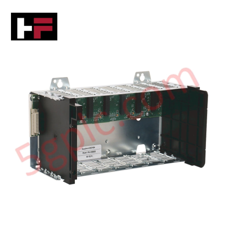
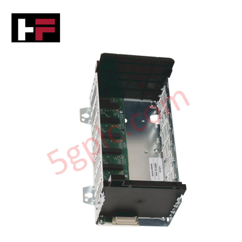
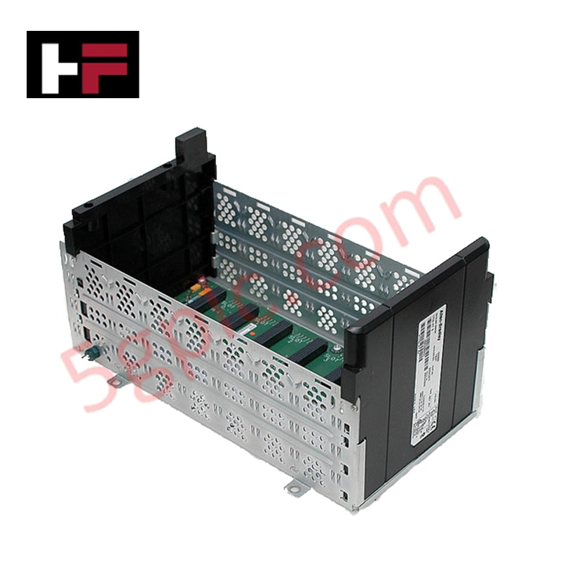
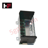
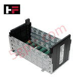
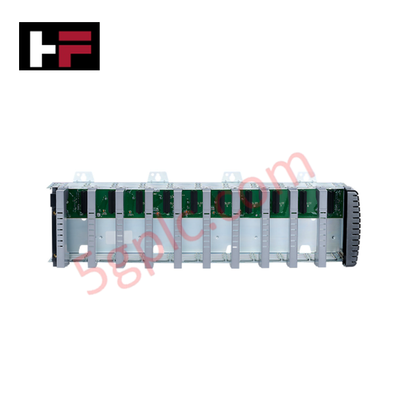
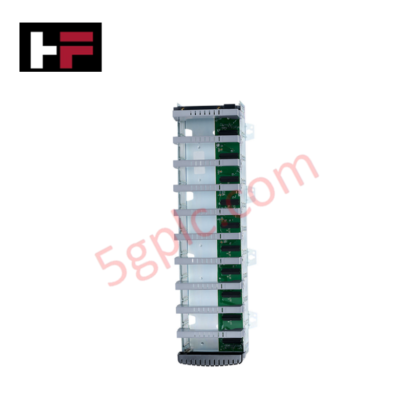
The Allen-Bradley 1756-A7XT acts as a heavy-duty, 7-slot extended temperature (XT) backplane chassis engineered for the ControlLogix programmable automation controller (PAC) platform. This high-reliability hardware backbone distributes logical bus communication and low-voltage DC operating power across up to seven ControlLogix modules, including processors, industrial network cards, and specialized I/O slices.
Designed specifically to survive outside standard climate-conditioned control rooms, this chassis withstands aggressive thermal variations and harsh atmospheric conditions. We supply this product exclusively as a 100% brand new, original factory-sealed unit, which guarantees flawless backplane pin insulation, pristine conformal coating matrices, and uncompromised factory data integrity.
Technical Specifications
The following reference matrix details the electrical distribution capacities, slot layout, and physical profile of this 7-slot XT chassis:
| Parameter | Performance & System Specifications |
| Manufacturer | Allen-Bradley / Rockwell Automation |
| Part Number | 1756-A7XT |
| Product Family | ControlLogix XT Series |
| Product Type | Rugged Extended Temperature Chassis |
| Total Available Slots | 7 Module Slots |
| Chassis Power Consumption | 4.5 Watts |
| Backplane Current (5.1V DC) | 10 A Total Chassis Maximum / 6 A Individual Slot Maximum |
| Backplane Current (24V DC) | 2 A Total Chassis Maximum / 2 A Individual Slot Maximum |
| Control Classification | PLCs / Machine Control Hardware |
| Net Weight | 3.00 lbs (1.36 kg) |
Engineering Advantages
-
Defeats Extreme Thermal Degradation: The specialized "XT" manufacturing process upgrades the internal backplane traces and multi-layer fiberglass substrates. This construction prevents delamination and tracing fractures when exposed to radical thermal cycles, allowing engineers to mount the control rack directly inside unconditioned field panels near harsh processing equipment.
-
Prevents Bus Voltage Drops Under High I/O Loads: The robust backplane distribution rails deliver up to 10 Amperes of continuous 5.1V DC power across the slots. This massive current headroom prevents dangerous voltage sags when inserting high-density 32-point digital modules or complex analog processing cards, eliminating intermittent backplane communication dropouts.
-
Condenses Footprint for Mid-Sized Enclosures: The 7-slot form factor provides the ideal architectural sweet spot for remote drop installations. It offers ample expansion room for dual communication adapters and several I/O cards while cutting horizontal panel width requirements compared to standard 10-slot or 17-slot chassis models.
FAQs
-
Can I insert standard, non-XT ControlLogix modules into this 1756-A7XT chassis?
Yes, the physical slot dimensions and electrical pinouts match standard 1756 series hardware perfectly. However, the weakest link defines the total environmental rating of the cluster. Inserting a standard commercial module strips away the extended temperature capability of the system, restricting safe operational limits to standard commercial specifications.
-
What mounting steps prevent high-frequency electrical noise from corrupting the backplane data?
Technicians must fasten the chassis horizontally onto a flat, unpainted metal backplate using the designated heavy-gauge mounting tabs. Use internal-tooth star washers under the mounting bolts to scratch through any surface film, creating a solid, low-impedance metal-to-metal ground path that drains off parasitic electromagnetic interference (EMI).
-
Why does the specification list separate chassis limits and slot limits for the 5.1V DC bus?
The individual slot limit (6 A) protects the thin spring-loaded pins inside a single chassis connector slot from overheating. The total chassis limit (10 A) defines the maximum thermal load capacity of the master backplane power rails. You must calculate the combined current draw of all seven inserted modules to ensure the aggregate load stays below the 10 A ceiling.
Additional Information
- 100% Genuine Parts: All products are original and authentic, ensuring reliable industrial performance.
- 30-Day Refund Guarantee: Return any in-stock item within 30 days in original, unopened packaging for a full refund (excluding shipping and fees).
- 12-Month Warranty: Covers defects in materials or workmanship; excludes misuse, normal wear, or unauthorized modifications.
- Worldwide Shipping: We ship via USPS, UPS, FedEx, and DHL. Delivery times vary by country and may be subject to customs or import fees.
- Support & Contact: Technical and warranty assistance is available anytime. Contact us here: Contact.
- Purchase Guidance: Check product specifications and compatibility carefully before ordering to ensure proper application.
Tech & Buying Guide

Why Programmable Logic Controllers Drop into Stop Mode: An Expert Analysis
Industrial automation systems rely heavily on Programmable Logic Controllers (PLCs) to maintain uninterrupted production. When a PLC unexpectedly shifts from Run to Stop mode, whole manufacturing lines stall.
As control systems evolve across modern factory automation, understanding the root causes of these interruptions helps engineers minimize costly downtime. This technical guide breaks down why PLCs trip into Stop mode and provides practical strategies to mitigate system faults.

Understanding Root Causes of Unplanned PLC Stop Mode in Industrial Automation
Modern Programmable Logic Controllers manage execution through distinct operational states: Run, Stop, Start-Up, and Hold. During power-up, a controller initializes memory registers within Stop mode before briefly transitioning to Start-Up mode. During this phase, internal self-diagnostics evaluate system integrity across hardware and user programs. If the controller detects no critical faults, it enters Run mode to execute the control program continuously. However, any severe system anomaly forces the CPU back into Stop mode immediately to prevent erratic machine behavior across the plant floor.

Human-Machine Interface Design: Essential Guide to HMI Selection, Visualization, and Control System Integration
Human-Machine Interfaces (HMIs) serve as the primary operational window into complex industrial automation systems. Modern HMIs convert raw machine data into clear graphical displays, enabling operators to oversee entire manufacturing processes in real time. Instead of relying on physical control panels full of hardwired switches, engineers program interactive screens using intuitive graphics, dynamic color coding, and responsive touch interfaces. Over my 15 years in control systems engineering, I have observed HMIs transform from basic display screens into sophisticated command centers that drive operational efficiency across DCS and PLC environments.