


Product Details
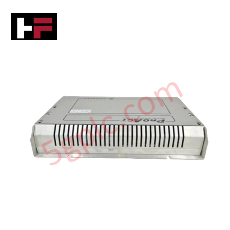
The Woodward 8400-016, also cataloged as the 8400-016 Speed Controller, operates as a dedicated hardware component for prime mover rotational velocity regulation within governing control platforms.
Hardware Specifications
| Parameter | Specification |
|---|---|
| Model | 8400-016 |
| Brand | Woodward |
| Origin | USA |
| Weight | 0.2 kg |
| Dimensions | 35.5 x 20 x 19 cm |
Actuator Loop Feedback Response
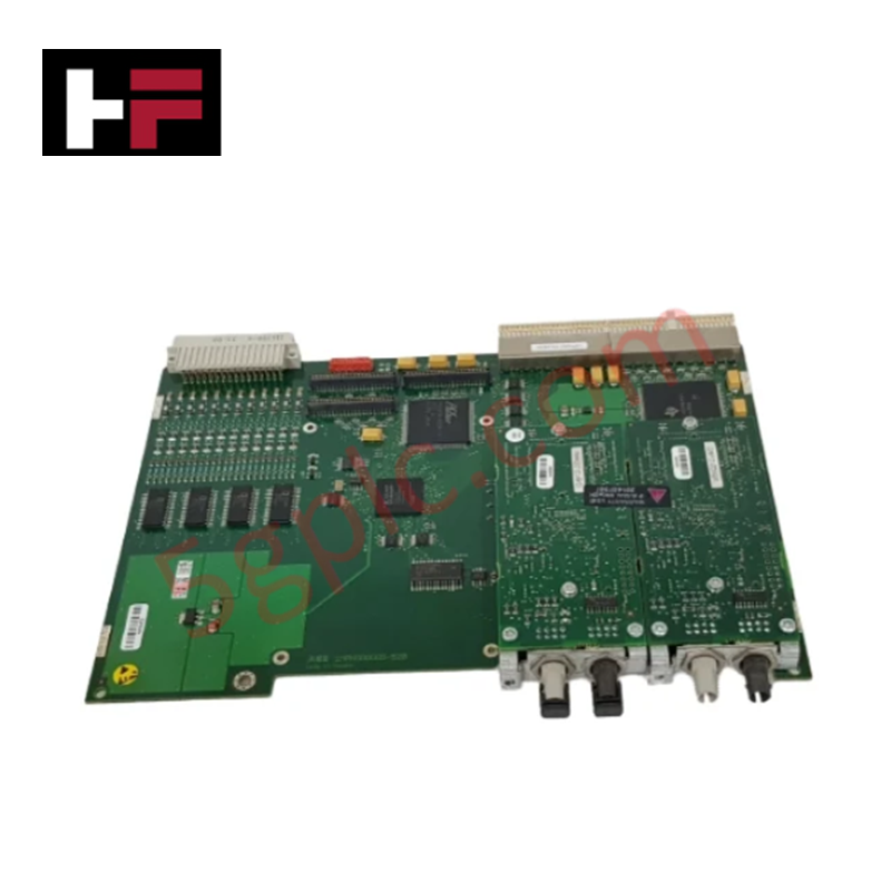
The 8400-016 speed controller modulates fuel delivery to the prime mover by processing speed sensor inputs to maintain a defined setpoint. Precise maintenance of the actuator loop feedback response is required to prevent instability, such as hunting or overshoot, during steady-state operation and load transients. The controller electronics are designed to process rapid frequency fluctuations and convert them into proportional drive signals for the attached actuator. Proper tuning of the gain and derivative terms within the internal feedback loop is necessary to compensate for the mechanical time constant of the fuel system, ensuring that the control output remains synchronized with the engine's dynamic response characteristics.
Frequently Asked Questions
Q: Is this controller compatible with redundant actuator configurations?
A: Compatibility with redundant actuator configurations depends on the specific wiring harness and control system architecture. Consult the integration manual to determine if the 8400-016 output stage supports parallel or master-slave driver operation.
Q: What are the primary considerations for serial communication setup?
A: When interfacing with the 8400-016, ensure that the communication cable utilizes shielded twisted-pair conductors. Signal integrity is contingent upon keeping the serial bus routing isolated from high-voltage AC lines to prevent induced noise on the data stream.
Field Installation Guidelines
- Mounting: Secure the controller housing within an industrial enclosure. Ensure the mounting orientation allows for adequate convective airflow over the chassis surfaces to dissipate internal heat.
- Wiring: Use shielded cabling for all speed sensor inputs and actuator outputs. Terminate the shield drain wire to the cabinet common ground point at only one end to prevent the formation of ground loops.
- Connection: Verify all terminal assignments against the system schematics prior to applying power. Ensure that the wire gauge is sufficient to carry the required actuator current without excessive voltage drop.
- Validation: Upon installation, perform a static check of the speed sensor input signal to ensure it is clear of electrical noise. Configure the control parameters according to the prime mover's idle and full-load speed requirements before initiating the first start sequence.
Additional Information
- 100% Genuine Parts: All products are original and authentic, ensuring reliable industrial performance.
- 30-Day Refund Guarantee: Return any in-stock item within 30 days in original, unopened packaging for a full refund (excluding shipping and fees).
- 12-Month Warranty: Covers defects in materials or workmanship; excludes misuse, normal wear, or unauthorized modifications.
- Worldwide Shipping: We ship via USPS, UPS, FedEx, and DHL. Delivery times vary by country and may be subject to customs or import fees.
- Support & Contact: Technical and warranty assistance is available anytime. Contact us here: Contact.
- Purchase Guidance: Check product specifications and compatibility carefully before ordering to ensure proper application.


Tech & Buying Guide

Mastering Functional Safety Terminology in Industrial Automation
In modern process control and factory automation, managing operational risk is a top engineering priority. High-speed machinery, high-pressure vessels, and continuous processes present constant hazards to personnel and equipment. Modern plant operations rely heavily on functional safety strategies to mitigate these risks. This guide breaks down the essential functional safety terminology that every control systems engineer should master.

Understanding Dry Contacts in PLC Wiring: An Industrial Automation Guide
Mastering contact switching principles is essential for reliable control panels. Field devices and PLCs interface through dry or wet contacts. This technical guide examines the mechanics of dry contacts, explores their wiring architectures, and evaluates their key advantages in industrial automation.

Ultimate Commissioning Checklist for Industrial Automation Systems: An Engineering Guide
Commissioning is the most decisive phase of an industrial automation project, transforming control hardware and software into an operational facility. Thorough testing prevents costly startup delays and builds customer confidence. This guide covers essential checklists, electrical standards, and best practices.