


Product Details
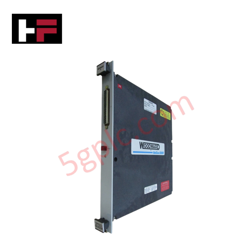
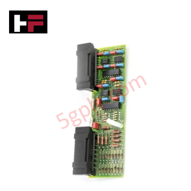
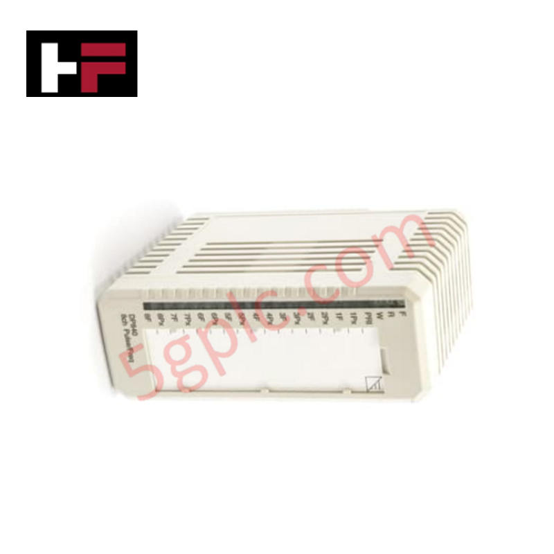
Configured for high-precision rotational velocity monitoring in control platforms, the Woodward 5464-658 (5464-658 Digital Speed Sensor Module) provides direct physical/electrical execution of MPU and proximity probe signal acquisition and data conversion.
Hardware Specifications
| Parameter | Specification |
|---|---|
| Model | 5464-658 |
| Brand | Woodward |
| Origin | USA |
| Input Channels | 4 Speed Channels |
| Input Types | Passive MPU or Proximity Probe |
| Filter Time Constant | 8 ms or 16 ms (selectable) |
| Min Detection | 0.5 Hz |
Actuator Loop Feedback Response
The 5464-658 module processes input signals from magnetic pickup units (MPUs) or proximity probes to determine rotational speed for prime mover control. The module architecture incorporates selectable filtering time constants of 8 ms or 16 ms to stabilize speed measurement within the application control loop. Accurate speed feedback is required for the governor's actuator loop feedback response, particularly during transient load rejection or rapid acceleration events. By eliminating the need for potentiometer-based calibration, the module maintains a consistent speed measurement profile, directly supporting the stability of fuel actuator or steam valve positioning algorithms. The software-defined minimum detection threshold is established at one-fiftieth of the configured speed range, with an absolute monitoring floor of 0.5 Hz.
Frequently Asked Questions
Q: Can the four input channels support mixed sensor types simultaneously?
A: Yes, each of the four channels can independently accept either a passive magnetic pickup unit (MPU) or a proximity probe. Users may utilize any combination of these sensor types across the four available input channels.
Q: How does the module handle a failed speed sensor at low rotational speeds?
A: The software control logic continuously monitors the input signal. The detection of a failed speed sensor is integrated into the monitoring logic to prevent overspeed conditions caused by slow update times, ensuring the control system transitions to a safe state if an input signal is lost.
Field Installation Guidelines
- Mounting: Secure the module within the designated rack slot, ensuring the backplane connector is fully seated to maintain electrical continuity.
- Signal Wiring: Use high-quality shielded twisted-pair cabling for all MPU and proximity probe connections to mitigate electromagnetic interference. Terminate shields at the chassis ground point to ensure noise immunity.
- Software Configuration: Select the appropriate filter time constant (8 ms for standard applications or 16 ms for low-speed applications) via the application software to optimize the signal-to-noise ratio of the speed data.
- Validation: Perform a static check of the MPU or proximity probe air gap and signal amplitude. During commissioning, compare the module's speed reading against a secondary calibrated reference to verify measurement accuracy across the operating speed range.
Additional Information
- 100% Genuine Parts: All products are original and authentic, ensuring reliable industrial performance.
- 30-Day Refund Guarantee: Return any in-stock item within 30 days in original, unopened packaging for a full refund (excluding shipping and fees).
- 12-Month Warranty: Covers defects in materials or workmanship; excludes misuse, normal wear, or unauthorized modifications.
- Worldwide Shipping: We ship via USPS, UPS, FedEx, and DHL. Delivery times vary by country and may be subject to customs or import fees.
- Support & Contact: Technical and warranty assistance is available anytime. Contact us here: Contact.
- Purchase Guidance: Check product specifications and compatibility carefully before ordering to ensure proper application.
Tech & Buying Guide
Mastering Functional Safety Terminology in Industrial Automation
In modern process control and factory automation, managing operational risk is a top engineering priority. High-speed machinery, high-pressure vessels, and continuous processes present constant hazards to personnel and equipment. Modern plant operations rely heavily on functional safety strategies to mitigate these risks. This guide breaks down the essential functional safety terminology that every control systems engineer should master.

Understanding Dry Contacts in PLC Wiring: An Industrial Automation Guide
Mastering contact switching principles is essential for reliable control panels. Field devices and PLCs interface through dry or wet contacts. This technical guide examines the mechanics of dry contacts, explores their wiring architectures, and evaluates their key advantages in industrial automation.

Ultimate Commissioning Checklist for Industrial Automation Systems: An Engineering Guide
Commissioning is the most decisive phase of an industrial automation project, transforming control hardware and software into an operational facility. Thorough testing prevents costly startup delays and builds customer confidence. This guide covers essential checklists, electrical standards, and best practices.