


Product Details
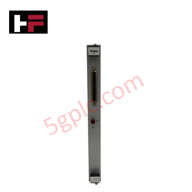
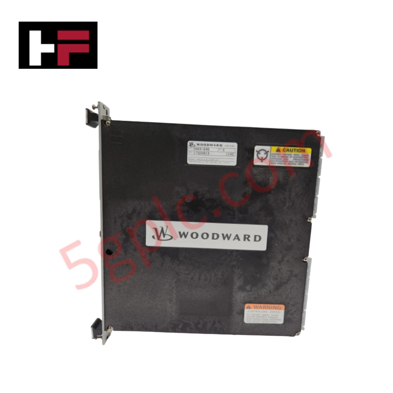
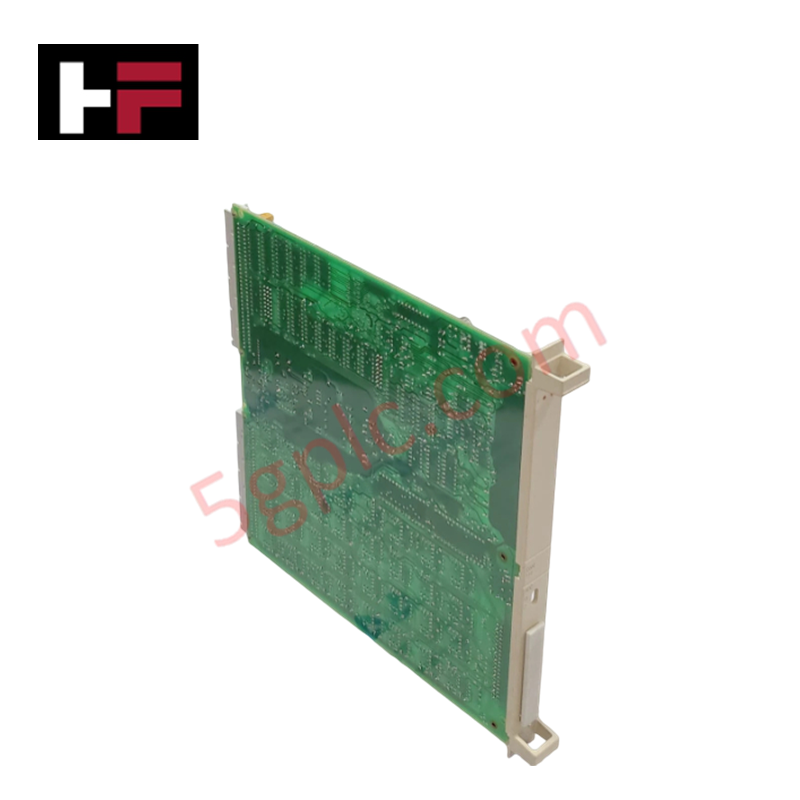
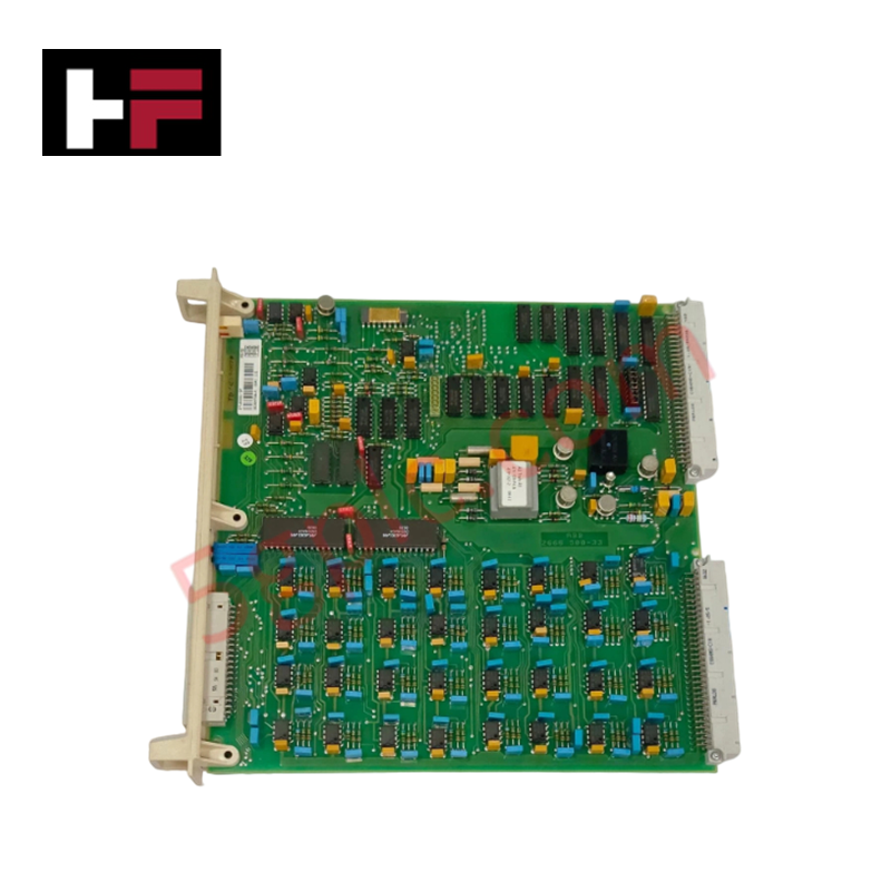
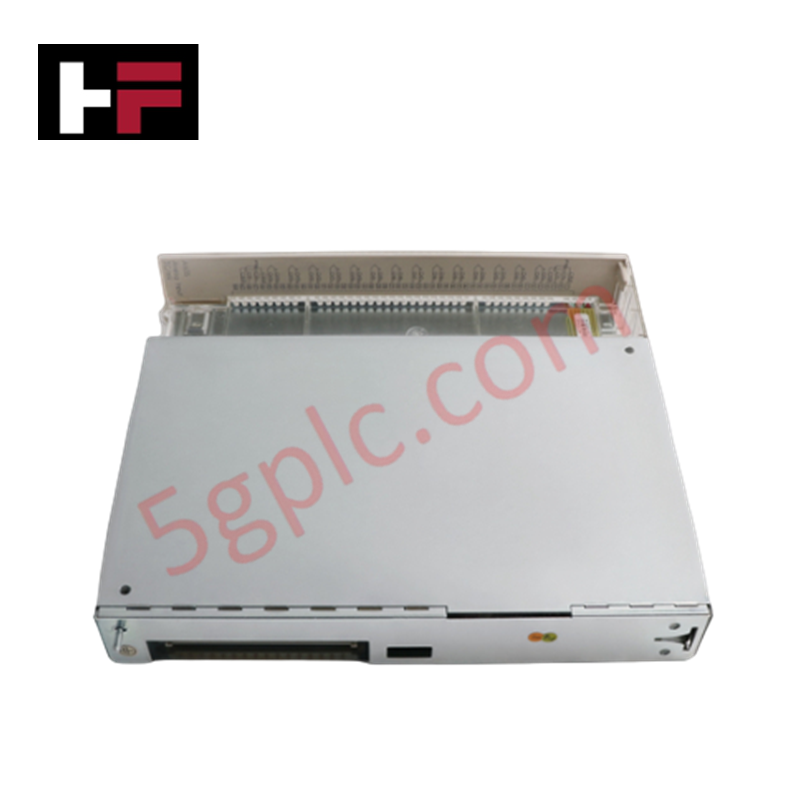
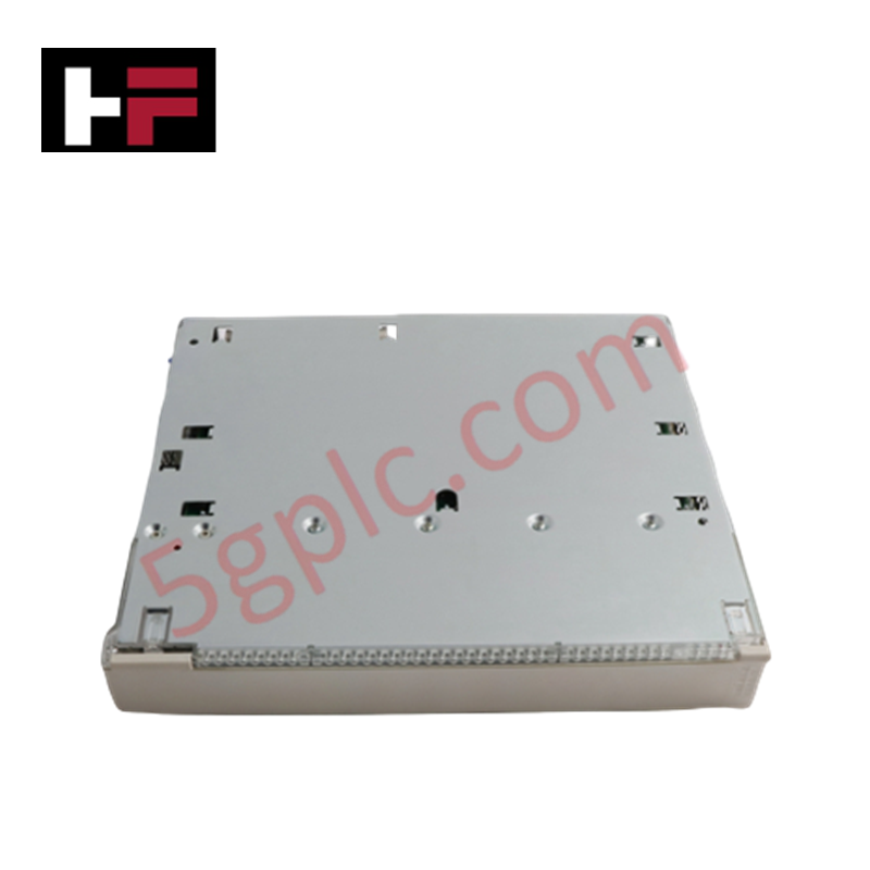
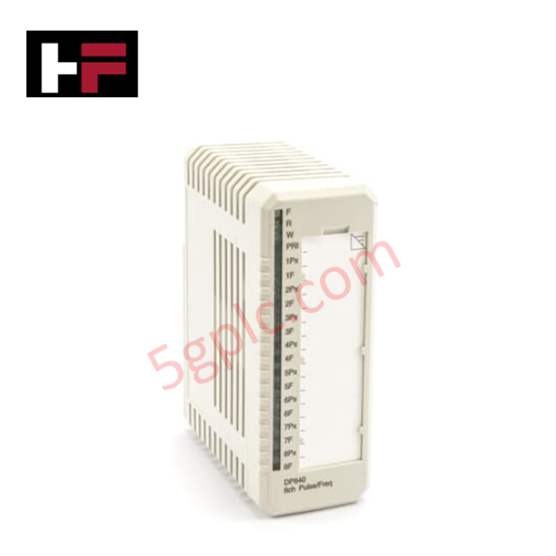
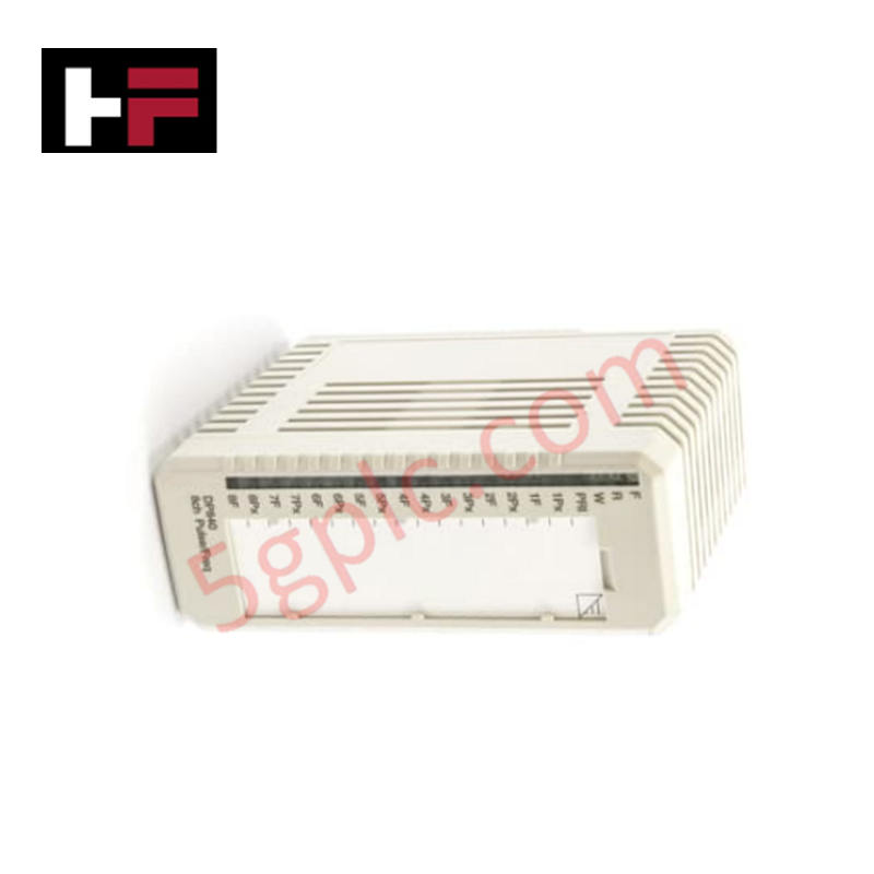
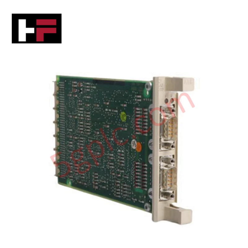
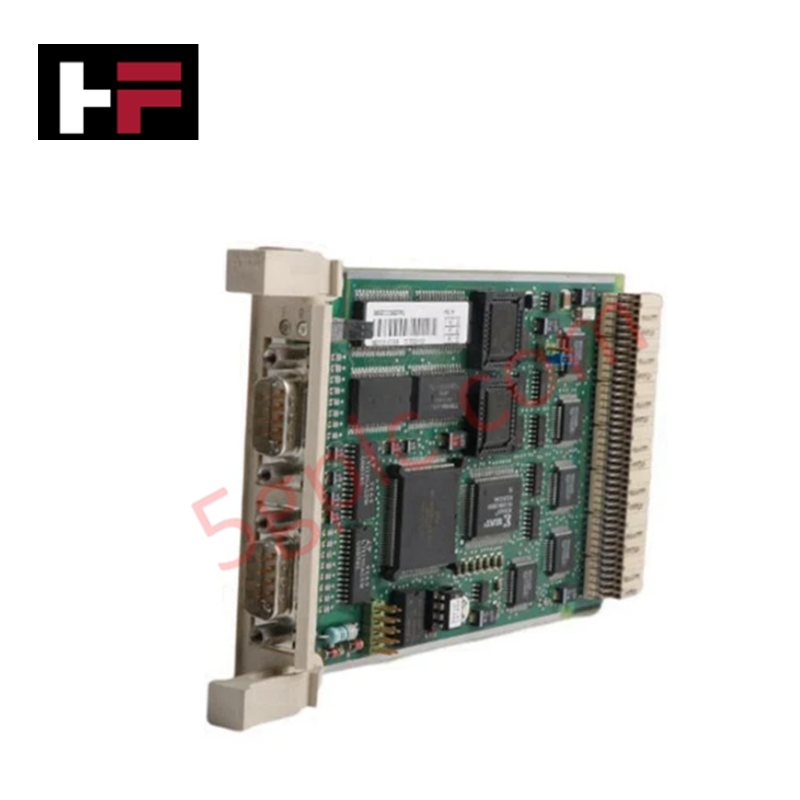
Configured for precision signal output in gas turbine control platforms, the Woodward 5464-648 (5464-648 Analog 8-Channel Output Module) provides direct physical/electrical execution of 4-20 mA and voltage control signals.
Hardware Specifications
| Parameter | Specification |
|---|---|
| Model | 5464-648 |
| Brand | Woodward |
| Origin | USA |
| Weight | 0.91 kg |
| Dimensions | 16 x 16 x 12 cm |
| Channels | 8 Independent channels |
| Signal Types | 4-20 mA, 0-10 V |
| Supported Protocols | Modbus, Profibus, EtherCAT |
Actuator Loop Feedback Response
The 5464-648 module utilizes high-resolution digital-to-analog conversion to facilitate precise positioning of turbine inlet valves and actuators. Each of the eight channels operates independently, allowing for granular control of auxiliary gas turbine components. The response characteristics of the actuator control loop are governed by the host controller's scan cycle and the module's internal conversion latency. To ensure loop stability, output signals must be monitored via the control system's feedback inputs, confirming the mechanical position of the valve aligns with the commanded current or voltage output.
Frequently Asked Questions
Q: Is the 5464-648 capable of hot-swapping within the control rack?
A: Hot-swapping capabilities are dependent on the specific turbine control rack backplane architecture. Refer to the primary system documentation to determine if the power-up state of the module upon re-insertion will cause an unintended actuator movement.
Q: Are the analog outputs galvanically isolated from the communication backplane?
A: The module supports standard industrial integration. It is recommended to employ signal isolators if the field actuator loops share a common potential with high-noise electrical equipment or if ground loops are identified during commissioning.
Field Installation Guidelines
- Physical Mounting: Ensure the module is properly aligned with the chassis connectors before engagement. Use the provided extraction mechanism to seat the module firmly into the backplane.
- Wiring Standards: Utilize shielded, twisted-pair cabling for all 4-20 mA analog output runs to mitigate electromagnetic interference. Ground the cable shield at the control cabinet side only to prevent ground loops.
- Loop Verification: Prior to enabling the control software, use a calibrated process meter to verify the signal output at the field terminal blocks for each of the eight channels.
- Configuration: Utilize the manufacturer-provided software tools to define the output scaling for each channel and confirm that the register mapping matches the host controller (PLC/DCS) memory map.
Additional Information
- 100% Genuine Parts: All products are original and authentic, ensuring reliable industrial performance.
- 30-Day Refund Guarantee: Return any in-stock item within 30 days in original, unopened packaging for a full refund (excluding shipping and fees).
- 12-Month Warranty: Covers defects in materials or workmanship; excludes misuse, normal wear, or unauthorized modifications.
- Worldwide Shipping: We ship via USPS, UPS, FedEx, and DHL. Delivery times vary by country and may be subject to customs or import fees.
- Support & Contact: Technical and warranty assistance is available anytime. Contact us here: Contact.
- Purchase Guidance: Check product specifications and compatibility carefully before ordering to ensure proper application.
Tech & Buying Guide

Mastering Functional Safety Terminology in Industrial Automation
In modern process control and factory automation, managing operational risk is a top engineering priority. High-speed machinery, high-pressure vessels, and continuous processes present constant hazards to personnel and equipment. Modern plant operations rely heavily on functional safety strategies to mitigate these risks. This guide breaks down the essential functional safety terminology that every control systems engineer should master.

Understanding Dry Contacts in PLC Wiring: An Industrial Automation Guide
Mastering contact switching principles is essential for reliable control panels. Field devices and PLCs interface through dry or wet contacts. This technical guide examines the mechanics of dry contacts, explores their wiring architectures, and evaluates their key advantages in industrial automation.

Ultimate Commissioning Checklist for Industrial Automation Systems: An Engineering Guide
Commissioning is the most decisive phase of an industrial automation project, transforming control hardware and software into an operational facility. Thorough testing prevents costly startup delays and builds customer confidence. This guide covers essential checklists, electrical standards, and best practices.