


Product Details
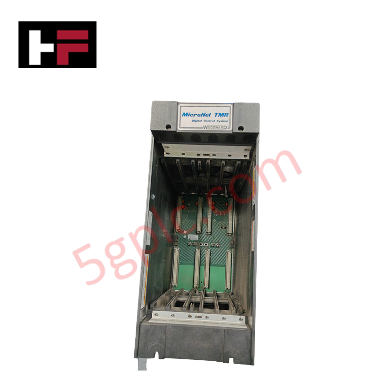
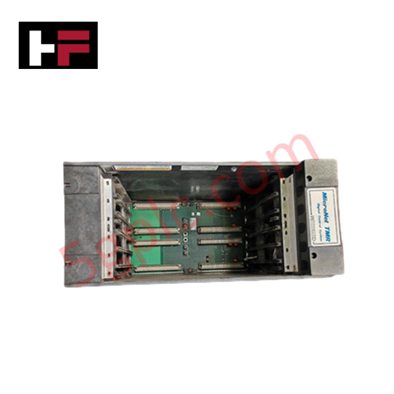
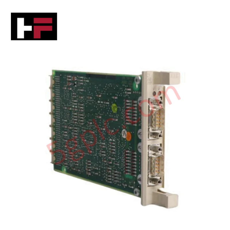
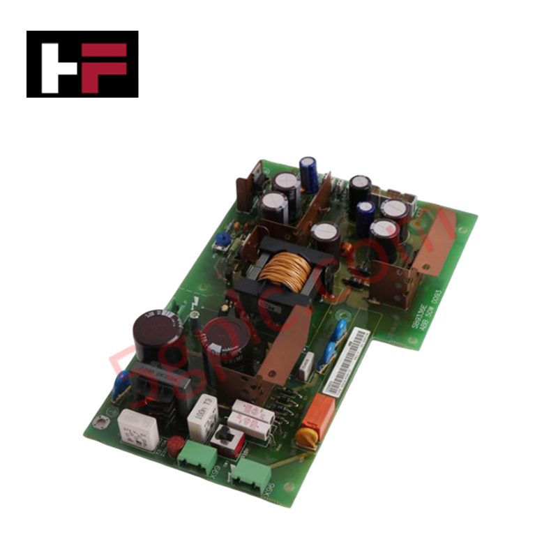
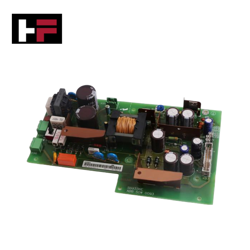
Configured for power distribution in TMR control architectures, the Woodward 5453-277 (5453-277 TMR Power Supply Chassis) provides direct physical execution of redundant module hosting and energy delivery within MicroNet platforms.
Hardware Specifications
| Parameter | Specification |
|---|---|
| Model | 5453-277 |
| Brand | Woodward |
| Origin | USA |
| Module Capacity | 2 redundant TMR modules |
| Chassis Configuration | Single or dual chassis options |
Actuator Loop Feedback Response and Thermal Heat Sink Dissipation Profiles
The 5453-277 chassis acts as the primary backplane interface for MicroNet power distribution, supporting load-sharing capabilities across redundant supply modules. The design accommodates low voltage DC, AC/DC, and high voltage AC/DC module versions to meet specific site power requirements. Thermal heat sink dissipation profiles must be maintained through adequate cabinet airflow, as the chassis supports the energy demands of Kernel PS modules. Proper integration ensures that the fail-safe mechanism remains active, allowing for continuous power delivery even during a single module fault condition. Actuator loop feedback response is maintained by providing a stable, regulated energy source to the system kernels, preventing voltage sags during transient power demands.
Frequently Asked Questions
Q: Can the chassis be configured for a single-module operation in a TMR environment?
A: While the chassis supports redundant module hosting, the TMR architecture requires full module complement to ensure fail-safe operation. Single-module configuration eliminates the redundancy mechanism and is not recommended for safety-critical TMR applications.
Q: Is this chassis compatible with all Woodward MicroNet power supply module revisions?
A: The chassis is designed for standard MicroNet TMR power supply modules. Compatibility with specific module part numbers should be verified against the site-specific system manual to ensure pin-out and voltage rating alignment.
Field Installation Guidelines
- Mounting: Secure the chassis within the control cabinet using the standard mounting provisions. Ensure the backplane interface is clear of debris before seating the power supply modules.
- Module Seating: Insert power supply modules firmly into the chassis slots until the retention mechanisms engage. Ensure the modules are fully seated to provide robust electrical connection to the backplane.
- Wiring: Terminate main power feeds to the chassis inputs according to the voltage requirements of the installed modules (low voltage DC, AC, or high voltage DC). Verify wire gauges conform to local electrical codes for the specified current load.
- Redundancy Verification: After installation, monitor the chassis health status via the system diagnostic interface to confirm that both power supply modules are active and participating in load sharing.
Additional Information
- 100% Genuine Parts: All products are original and authentic, ensuring reliable industrial performance.
- 30-Day Refund Guarantee: Return any in-stock item within 30 days in original, unopened packaging for a full refund (excluding shipping and fees).
- 12-Month Warranty: Covers defects in materials or workmanship; excludes misuse, normal wear, or unauthorized modifications.
- Worldwide Shipping: We ship via USPS, UPS, FedEx, and DHL. Delivery times vary by country and may be subject to customs or import fees.
- Support & Contact: Technical and warranty assistance is available anytime. Contact us here: Contact.
- Purchase Guidance: Check product specifications and compatibility carefully before ordering to ensure proper application.


Tech & Buying Guide
Mastering Functional Safety Terminology in Industrial Automation
In modern process control and factory automation, managing operational risk is a top engineering priority. High-speed machinery, high-pressure vessels, and continuous processes present constant hazards to personnel and equipment. Modern plant operations rely heavily on functional safety strategies to mitigate these risks. This guide breaks down the essential functional safety terminology that every control systems engineer should master.

Understanding Dry Contacts in PLC Wiring: An Industrial Automation Guide
Mastering contact switching principles is essential for reliable control panels. Field devices and PLCs interface through dry or wet contacts. This technical guide examines the mechanics of dry contacts, explores their wiring architectures, and evaluates their key advantages in industrial automation.

Ultimate Commissioning Checklist for Industrial Automation Systems: An Engineering Guide
Commissioning is the most decisive phase of an industrial automation project, transforming control hardware and software into an operational facility. Thorough testing prevents costly startup delays and builds customer confidence. This guide covers essential checklists, electrical standards, and best practices.