










Product Details
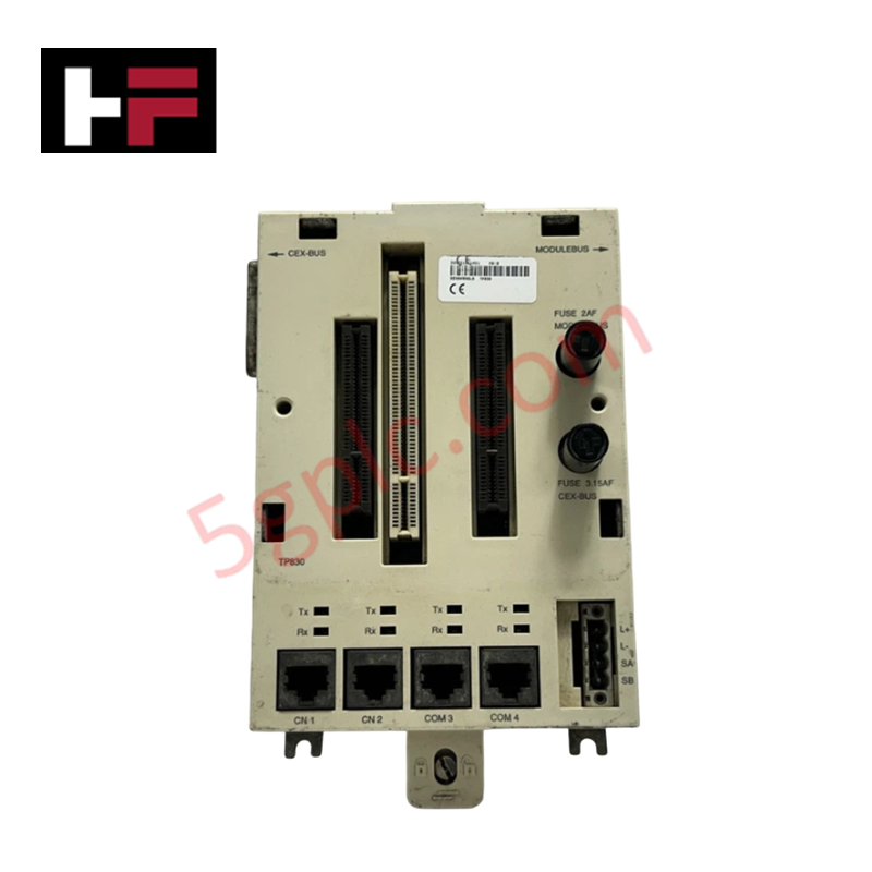
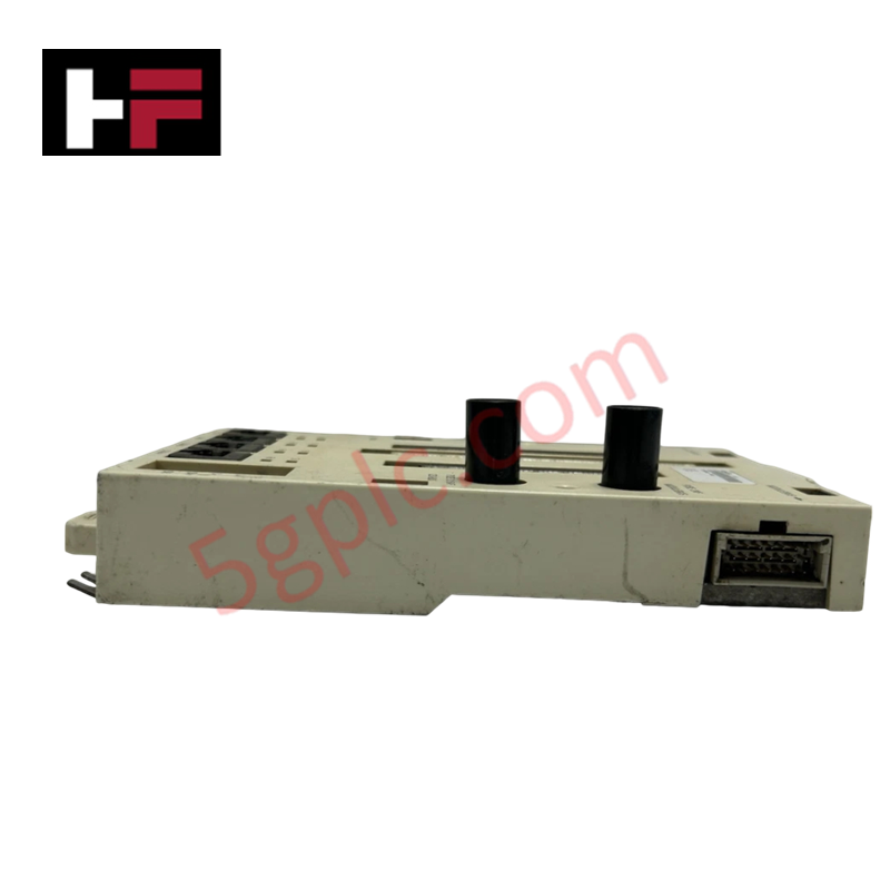
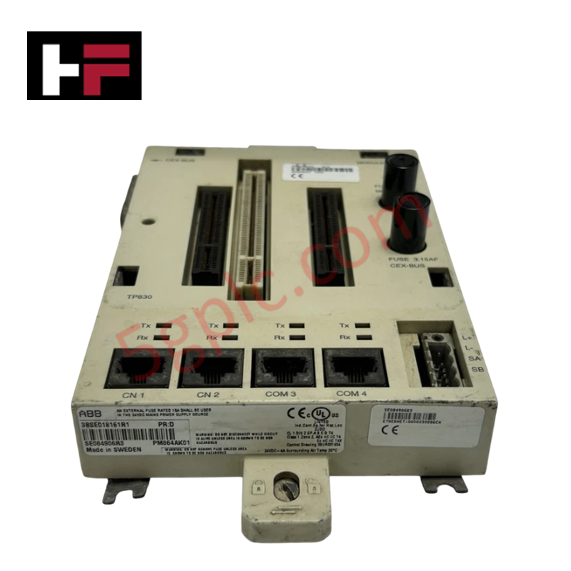
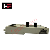
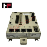
The ABB TP830 3BSE018114R1, also cataloged as the TP830 Baseplate, operates as a dedicated hardware component for structural mounting and backplane bus interfacing within AC 800M controller configurations.
Hardware Specifications
| Parameter | Specification |
|---|---|
| Model | TP830 (Product ID: 3BSE018114R1) |
| Brand | ABB |
| Origin | United States |
| Weight | 0.5 kg (1 lb 1 oz) |
| Dimensions | 12.7 cm x 7.6 cm x 20.3 cm (5.0 in x 3.0 in x 8.0 in) |
| Operating Temp | 0 to +55 deg C |
| Power Consumption | Passive backplane assembly (N/A) |
| Product Type | Baseplate for PM8xx Processor Modules |
| Processor Compatibility | PM851, PM856, PM864, PM865, PM866 |
| Customs Tariff | 8538908180 |
Backplane Bus Communication Velocity and System Integration
The TP830 baseplate serves as the physical and electrical grounding foundation for AC 800M processor modules, providing internal bus lines for high-velocity signal propagation between controller units and redundant power inputs. Internal trace routing supports deterministic backplane bus communication velocity and firmware flash compatibility during online module insertion, preventing control loop disruption across active processor racks.
Frequently Asked Questions
Q: Can the TP830 baseplate be hot-swapped while the processor module is actively executing control logic?
A: No. Removing or replacing the baseplate breaks physical power rail continuity and backplane bus termination, which disrupts signal execution across the connected processor rack.
Q: How is electrical shielding and grounding maintained across the baseplate assembly?
A: Chassis ground is established directly through internal metallic contacts engaging the mounting surface and DIN-rail, ensuring proper noise isolation for backplane communication.
Field Installation Guidelines
- Mount the baseplate firmly on a standard grounded 35 mm DIN-rail or metal sub-panel before inserting any processor modules.
- Inspect all pin connections on the backplane interface header to ensure no pins are bent or contaminated with field debris.
- Align the compatible processor module (PM851, PM856, PM864, PM865, or PM866) with the guide rails and press firmly until side locking mechanisms engage fully.
- Verify low-impedance connection between the mounting plate ground terminal and the local cabinet protective earth (PE) busbar prior to applying system power.
Additional Information
- 100% Genuine Parts: All products are original and authentic, ensuring reliable industrial performance.
- 30-Day Refund Guarantee: Return any in-stock item within 30 days in original, unopened packaging for a full refund (excluding shipping and fees).
- 12-Month Warranty: Covers defects in materials or workmanship; excludes misuse, normal wear, or unauthorized modifications.
- Worldwide Shipping: We ship via USPS, UPS, FedEx, and DHL. Delivery times vary by country and may be subject to customs or import fees.
- Support & Contact: Technical and warranty assistance is available anytime. Contact us here: Contact.
- Purchase Guidance: Check product specifications and compatibility carefully before ordering to ensure proper application.









Tech & Buying Guide

Spatial Computing in Industrial Automation: Elevating PLC and DCS Operations with AR and VR
Industry 4.0 integrates digital intelligence into field operations, transforming factory automation landscapes worldwide. Spatial technologies—specifically Augmented Reality (AR) and Virtual Reality (VR)—redefine how engineers interact with industrial control systems. By bridging computer-generated CAD models with real-time operational technology (OT) data, immersive displays enable intuitive monitoring, rapid diagnostics, and safer maintenance across complex processing facilities.

Master Acceptance Testing: Understanding FAT and SAT in Industrial Control Systems
Factory Acceptance Testing (FAT) and Site Acceptance Testing (SAT) serve as critical quality assurance gateways in complex industrial control systems. Both procedures verify that programmable logic controllers (PLCs), distributed control systems (DCS), and associated field devices meet strict functional specifications. However, executing these tests effectively requires clear delineation between off-site staging and final field commissioning.

Industrial Networking Essentials: Demystifying Hubs, Switches, and Routers in Control Systems
Industrial automation relies heavily on robust networking infrastructure to connect programmable logic controllers (PLCs), distributed control systems (DCS), and human-machine interfaces (HMIs). Modern factory automation environments generate vast amounts of real-time operational data across deterministic networks. Understanding the structural differences between hubs, switches, and routers ensures optimal traffic segmentation, minimizes latency, and maintains high network availability.