










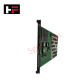
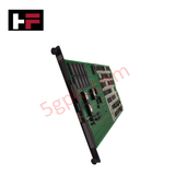
Product Details
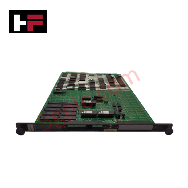
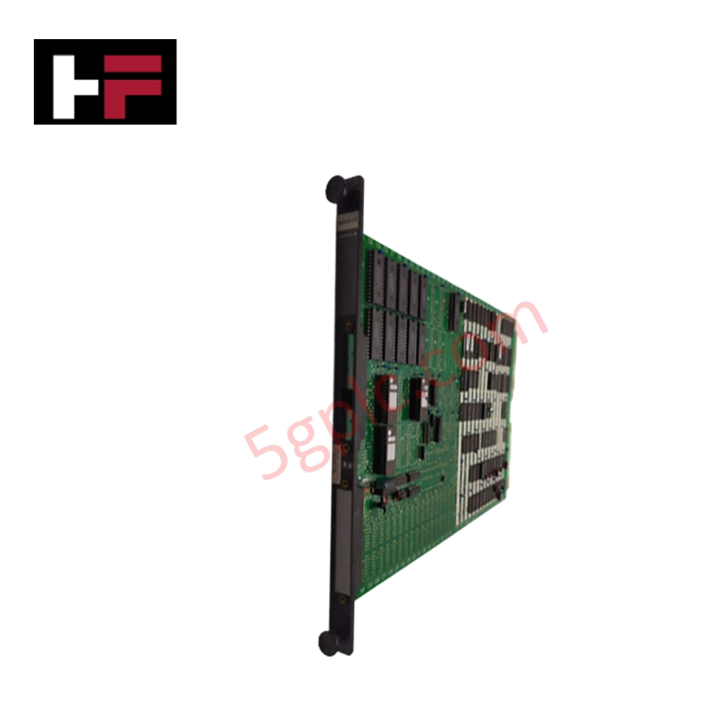
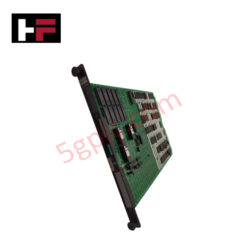
Configured for power conversion and backplane logic supply in CENTUM VP and CS 3000 networks, the Yokogawa MS05*B (MS05 Power Supply Module) provides direct physical/electrical execution. The hardware converts incoming 24 VDC power into regulated 5 VDC rails to drive local processing subassemblies within Field Control Unit (FCU) subracks.
Hardware Specifications
| Parameter | Specification |
|---|---|
| Model | MS05*B |
| Brand | Yokogawa |
| Origin | Japan |
| Weight | 0.35 kg |
| Dimensions | 120 mm x 25 mm x 130 mm |
| Operating Temp | 0 to 60 deg C |
| Power Consumption | 30 W |
| Input Voltage | 24 VDC nominal (20 to 30 VDC range) |
| Output Voltage | 5 VDC |
| Output Current | Up to 5 A |
| Isolation | 1500 VAC (input-to-output, 1 min) |
| Protection Features | Overcurrent, overvoltage, short-circuit protection |
| System Compatibility | CENTUM VP, CS 3000 |
Power Conditioning & Channel Isolation
The power supply module accepts a nominal 24 VDC input and utilizes internal switching regulator topologies to generate a stabilized 5 VDC bus line capable of sourcing up to 5 A. To maintain system reference ground stability and decouple the internal FCU logic from upstream electrical transients, the hardware incorporates a galvanic isolation layer rated at 1500 VAC between input and output networks. Integrated circuits feature automated overcurrent, overvoltage, and short-circuit protection arrays alongside 4-20 mA HART loop protocol compatibility on connected loop channels. Real-time diagnostics are output through front-panel LED indicators displaying RUN, FAIL, and input status.
Frequently Asked Questions
Q: How does the MS05*B handle load sharing when deployed in dual-redundant configurations?
A: When two modules occupy redundant slots in the FCU backplane, internal diode-ORing logic balances the current demand across both units; if one module experiences an internal breakdown, the parallel unit assumes the full 5 A current load without a voltage sag on the 5 VDC logic bus.
Q: What is the significance of the front-panel FAIL LED illuminating while the input voltage remains within the 20 to 30 VDC range?
A: An active FAIL LED under nominal input conditions indicates that secondary internal diagnostics have detected an out-of-spec voltage drop on the 5 VDC output rail or an over-temperature state.
Field Installation Guidelines
- Subrack Alignment: Align the module card rails with the designated slot tracks inside the FCU chassis. Slide the unit inward until the backplane connectors fully seat, then tighten retaining screws to lock the assembly against vibration.
- Input Power Termination: Route incoming 24 VDC power lines through independent wire ducts, keeping them physically separated from high-voltage AC lines. Ensure terminal connection screws are tightened to standard engineering torque limits.
- Grounding Protocols: Connect the main chassis protective grounding wire directly to the cabinet ground bar using heavy-gauge copper conductors to minimize common-mode noise.
- Thermal Management: Maintain clear air convection passages above and below the FCU rack, ensuring cabinet ambient temperatures remain within 0 to 60 deg C under full load.
Additional Information
- 100% Genuine Parts: All products are original and authentic, ensuring reliable industrial performance.
- 30-Day Refund Guarantee: Return any in-stock item within 30 days in original, unopened packaging for a full refund (excluding shipping and fees).
- 12-Month Warranty: Covers defects in materials or workmanship; excludes misuse, normal wear, or unauthorized modifications.
- Worldwide Shipping: We ship via USPS, UPS, FedEx, and DHL. Delivery times vary by country and may be subject to customs or import fees.
- Support & Contact: Technical and warranty assistance is available anytime. Contact us here: Contact.
- Purchase Guidance: Check product specifications and compatibility carefully before ordering to ensure proper application.


Tech & Buying Guide

Understanding Siemens PLC Memory Cards: MMC, SMC, and SD Solutions in Industrial Automation
Memory management plays a pivotal role in maintaining control system reliability across modern manufacturing plants. Industrial control systems rely on specialized memory cards to store project logic, firmware updates, and retentive system data. Siemens uses several memory architectures, including Micro Memory Cards (MMC) and SIMATIC Memory Cards (SMC). Engineers must understand these hardware variations to ensure zero data loss and minimize downtime during maintenance routines.

Redefining Control Systems: The Rise of Flexible I/O Modules in Industrial Automation
Conventional input-output architectures often limit engineering agility and inflate long-term inventory costs. Today, Flexible Input/Output Modules (FIOM) are transforming how control system engineers design, commission, and maintain automation infrastructure. By allowing individual channel software configuration, FIOM technology bridges the gap between rigid hardware design and dynamic plant requirements.
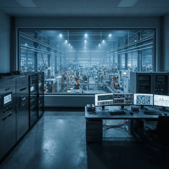
Understanding Modern SCADA Systems: Architecture, Communication Topologies, and Industrial Applications
Supervisory Control and Data Acquisition (SCADA) systems form the digital backbone of modern industrial automation. They collect critical field data, transmit signals across vast distances, and empower plant operators with real-time process visibility. Across modern infrastructures, SCADA solutions streamline centralized control and maintain continuous operational uptime.