












Product Details
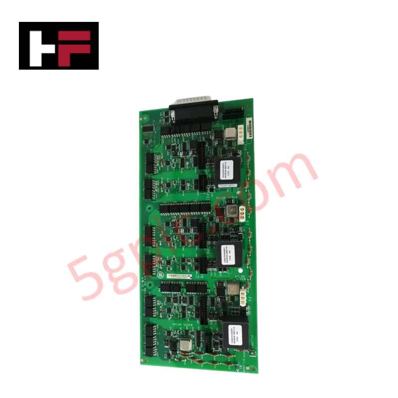
The GE IS210AEBIH3BBC, also cataloged as the IS210AEBIH3 Alternative Energy Bridge Interface, operates as a dedicated hardware component for bridge signal processing and power conversion data exchange within Mark VIe Wind Series architectures.
Hardware Specifications
| Parameter | Specification |
|---|---|
| Model | IS210AEBIH3BBC |
| Brand | GE (GE Energy) |
| Origin | USA |
| Dimensions | 10 cm x 10 cm x 2 cm |
| Operating Temp | -40 to 85 deg C |
| Power Consumption | 24 VDC external supply input |
| System Series | Mark VIe Wind Series |
| Product Type | Communication Modules |
| I/O Channels | Multiple digital and analog inputs/outputs |
| Protocols | RS485 and Ethernet communication |
| Electrical Protection | Integrated overvoltage and overcurrent protection |
Deterministic Networks & Backplane Communication Integrations
The IS210AEBIH3BBC interfaces directly with power electronic bridge assemblies to maintain real-time signal flow across Profinet / EtherNet/IP deterministic networks and dedicated RS485 serial paths. Internal signal distribution maintains maximum backplane bus communication velocity while routing field-level telemetry from multiple digital and analog I/O points back to the central controller.
I/O density scaling allows complex bridge monitoring circuits to interact seamlessly with onboard firmware flash compatibility structures. Built-in hardware mechanisms safeguard real-time transmission frames from transient spikes via integrated overvoltage and overcurrent suppression circuits.
Frequently Asked Questions
Q: What power input levels are required to operate the IS210AEBIH3BBC interface board?
A: The board requires a dedicated 24 VDC power supply input to drive its internal processing circuits, communication transceivers, and I/O channels.
Q: How does the module handle physical noise and voltage spikes on its communication interfaces?
A: The board includes built-in overvoltage and overcurrent protection circuitry engineered directly onto the terminal lines to isolate control electronics from field-side voltage transients.
Q: What serial and Ethernet protocols are supported for communication with the main rack?
A: The card incorporates dual onboard communication paths, supporting RS485 serial communication protocols alongside industrial Ethernet connections.
Field Installation Guidelines
- System Power Shutdown: Disconnect and isolate the 24 VDC primary power feed and backplane power source prior to starting board installation.
- Grounding Precautions: Connect an ESD grounding wrist strap to a verified bare-metal rack ground point before extracting the board from its anti-static packing.
- Physical Mounting: Align the 10 cm x 10 cm card with its mounting standoff locations or card guides inside the enclosure, ensuring mechanical alignment without flexing the board.
- Wiring and Cable Termination: Connect RS485 serial lines and Ethernet network cables to their designated ports. Secure field I/O connections, ensuring signal shields are grounded at the system earth bus bar.
- Initial Power Check: Verify input voltage polarity across the 24 VDC supply terminals before re-energizing the cabinet to avoid hardware damage.
Additional Information
- 100% Genuine Parts: All products are original and authentic, ensuring reliable industrial performance.
- 30-Day Refund Guarantee: Return any in-stock item within 30 days in original, unopened packaging for a full refund (excluding shipping and fees).
- 12-Month Warranty: Covers defects in materials or workmanship; excludes misuse, normal wear, or unauthorized modifications.
- Worldwide Shipping: We ship via USPS, UPS, FedEx, and DHL. Delivery times vary by country and may be subject to customs or import fees.
- Support & Contact: Technical and warranty assistance is available anytime. Contact us here: Contact.
- Purchase Guidance: Check product specifications and compatibility carefully before ordering to ensure proper application.


Tech & Buying Guide

Will PLCs Become Obsolete? The Future of Control Systems in Industry 4.0
Modern manufacturing is undergoing a rapid technological transformation driven by Industry 4.0 innovations. Technologies like Artificial Intelligence (AI), Machine Learning (ML), and the Industrial Internet of Things (IIoT) are dominating discussions across the factory automation sector. Consequently, many engineers wonder if these advanced digital tools will eventually replace traditional Programmable Logic Controllers (PLCs). However, evaluating the core physics of industrial operations reveals a very different reality for control systems.

Demystifying Open Platform Communication (OPC): The Backbone of Industrial Interoperability
Interoperability remains a cornerstone requirement for modern smart factories and process automation. Open Platform Communication (OPC) bridges the gap between disparate hardware platforms, control systems, and visualization software. By establishing a universal communication standard, OPC allows field controllers, SCADA platforms, and enterprise software from different vendors to exchange real-time data seamlessly.

Understanding Siemens PLC Memory Cards: MMC, SMC, and SD Solutions in Industrial Automation
Memory management plays a pivotal role in maintaining control system reliability across modern manufacturing plants. Industrial control systems rely on specialized memory cards to store project logic, firmware updates, and retentive system data. Siemens uses several memory architectures, including Micro Memory Cards (MMC) and SIMATIC Memory Cards (SMC). Engineers must understand these hardware variations to ensure zero data loss and minimize downtime during maintenance routines.