


Product Details
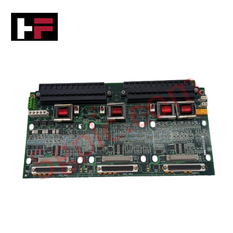
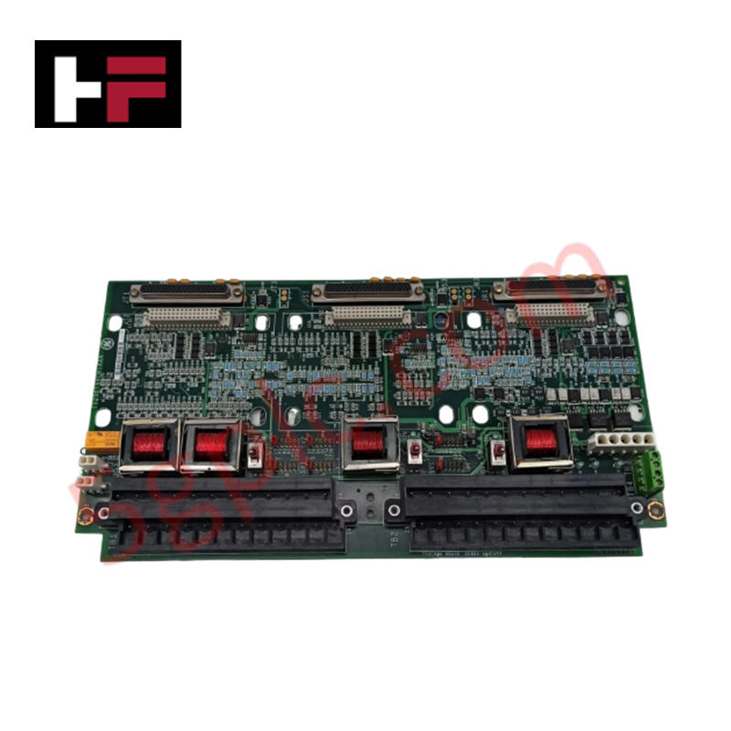
The GE IS200TSVCH1A, also cataloged as the IS200TSVCH1A Servo Input/Output Terminal Board, operates as a dedicated hardware component for electro-hydraulic actuator interface within Mark VIe control platforms. This module provides direct physical execution of servo valve control signals and LVDT (Linear Variable Differential Transformer) position feedback, supporting simplex, dual, and TMR control configurations.
Hardware Specifications
| Parameter | Specification |
|---|---|
| Model | IS200TSVCH1A |
| Brand | GE |
| Origin | USA |
| Dimensions | Standard terminal board form factor |
| Operating Temp | Standard industrial ambient range |
| Power Consumption | 28 V dc (via J28 socket) |
| Servo Channels | 2 electro-hydraulic valve interfaces |
| Compatibility | PSVO I/O pack, WSVO servo driver |
Backplane Bus Communication and Deterministic Networks
The IS200TSVCH1A facilitates deterministic servo control by managing the interface between the control system and external hydraulic actuators. The module is engineered for integration with the PSVO I/O pack and WSVO servo driver; it is strictly incompatible with VSVO processor hardware. Data integrity is maintained through dedicated LVDT feedback loops for valve positioning. Backplane bus communication velocity must be aligned with the PSVO pack’s requirements to ensure tight control loop stability. Users must verify firmware flash compatibility during initial configuration to prevent timing discrepancies in the servo drive loops. The board incorporates dual external trip plugs (JD1/JD2) to enable immediate safety-related de-energization of the servo circuitry.
Frequently Asked Questions
Q: Is the IS200TSVCH1A compatible with the VSVO servo processor?
A: No. The IS200TSVCH1A terminal board is specifically designed for use with the PSVO I/O pack and WSVO servo driver. Attempting to interface this board with a VSVO processor will cause signal mismatch and control failure.
Q: How is power supplied to the servo valves via this terminal board?
A: The servo valve supply voltage is provided through the J28 socket, which receives a 28 V dc input. Ensure this power source is stabilized and filtered to prevent induced noise in the LVDT feedback signals.
Field Installation Guidelines
- Mounting: Secure the terminal board within the control cabinet, ensuring sufficient clearance for the dense wiring required for servo and LVDT interfaces.
- Wiring: Route LVDT position feedback wiring in shielded, twisted-pair cables. Ground the cable shields at the terminal board side only to avoid ground loops that could degrade valve position measurement accuracy.
- Servo Interface: Verify the polarity of the servo valve connections. Improper phase or polarity alignment can cause actuator oscillation or instability in the valve control loop.
- Trip Plugs: Ensure JD1 and JD2 external trip plugs are properly seated. These connectors provide the physical disconnect path for the actuator; any looseness in these connections can result in erratic valve performance or intermittent trips.
Additional Information
- 100% Genuine Parts: All products are original and authentic, ensuring reliable industrial performance.
- 30-Day Refund Guarantee: Return any in-stock item within 30 days in original, unopened packaging for a full refund (excluding shipping and fees).
- 12-Month Warranty: Covers defects in materials or workmanship; excludes misuse, normal wear, or unauthorized modifications.
- Worldwide Shipping: We ship via USPS, UPS, FedEx, and DHL. Delivery times vary by country and may be subject to customs or import fees.
- Support & Contact: Technical and warranty assistance is available anytime. Contact us here: Contact.
- Purchase Guidance: Check product specifications and compatibility carefully before ordering to ensure proper application.
Tech & Buying Guide

Mastering the Factory Acceptance Test (FAT) for PLC Control Panels: An Expert Guide
The Factory Acceptance Test (FAT) is a vital milestone in industrial automation that ensures custom PLC panels meet exact design specifications before dispatch. This guide outlines the step-by-step FAT procedure and key industry best practices to prevent costly site delays and ensure long-term operational success.

Redundant Automation Systems: Ensuring Continuous Uptime in Critical Control Infrastructure
System reliability directly determines operational profitability across high stakes process industries. Modern industrial automation platforms must eliminate single points of failure to prevent catastrophic shutdowns. Deploying fault tolerant architecture safeguards complex facilities against unexpected hardware glitches, network disruptions, and maintenance outages.

Understanding Types of Noise in Electronic Circuits and Control Systems
Signal integrity directly determines measurement accuracy and loop stability across industrial automation environments. Electronic noise introduces unwanted stochastic interference into analog loops, sensor feedback lines, and digital fieldbus networks. Understanding how intrinsic electronic noise and external electromagnetic interference manifest allows control engineers to optimize signal conditioning and shield sensitive instrumentation effectively.