














Product Details
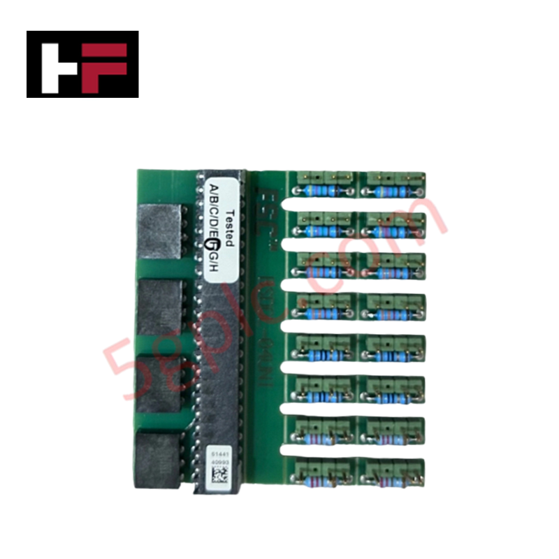
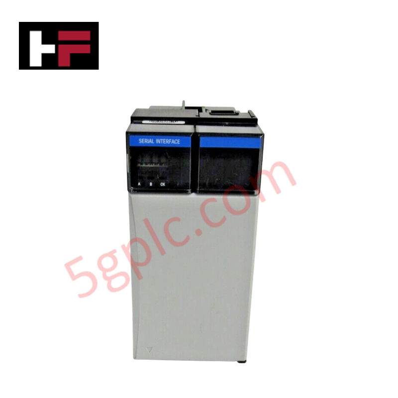
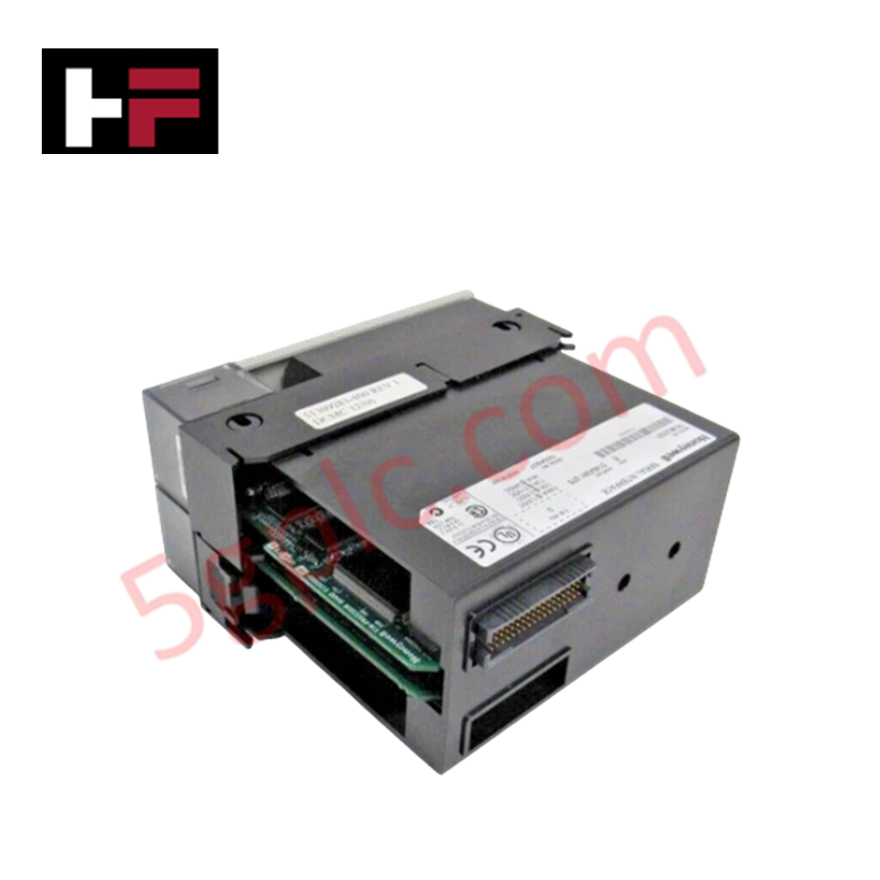
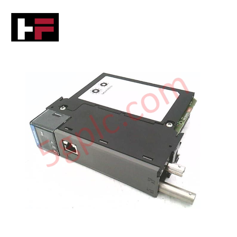
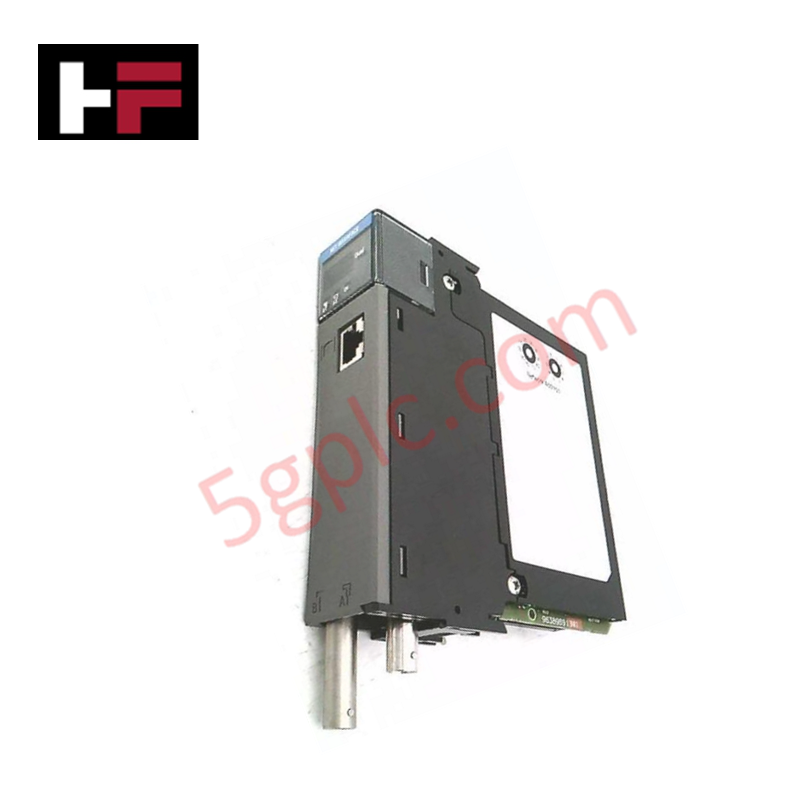
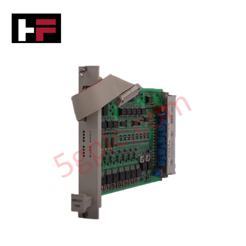
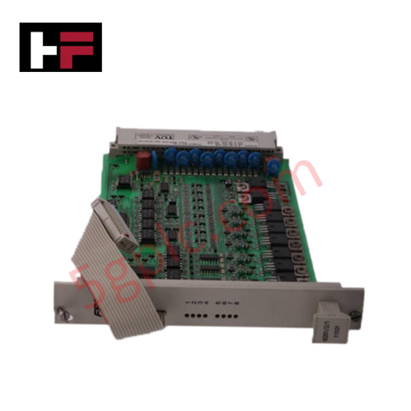
The Honeywell FS-BSDOL-04UNI, also cataloged as the FC-BSDOL-04UNI Range-Setting Module Set, operates as a dedicated hardware component for output loop range configuration and parameter scaling within Honeywell Safety Manager SC platforms.
Hardware Specifications
| Parameter | Specification |
|---|---|
| Model | FS-BSDOL-04UNI (FC-BSDOL-04UNI) |
| Brand | Honeywell |
| Origin | USA |
| Weight | 0.4 kg |
| Dimensions | 120 mm x 60 mm x 40 mm |
| Operating Temp | -20 to 70 deg C |
| Power Consumption | < 5 W |
| Operating Voltage | 24 VDC |
| Range Setting Resolution | Up to +/-0.5% accuracy |
| Channel Support | 4 loop-monitored output channels |
| Communication Interface | RS-485 |
| System Compatibility | Honeywell Safety Manager SC / SDOL systems |
Process Control & DCS Output Scaling Characteristics
The FS-BSDOL-04UNI range-setting module set mounts directly onto the programming connector (Px) of the IO backplane, providing direct hardware-level configuration for four loop-monitored output channels. Featuring integrated channel-to-channel isolation, the module preserves signal integrity across process output interfaces while executing high-accuracy parameter adjustments up to +/-0.5%. The onboard RS-485 communication link provides deterministic parameter transfer without interfering with active 4-20 mA HART loop protocol telemetry or field output driver circuits.
Frequently Asked Questions
Q: How is the FS-BSDOL-04UNI module physically connected to the I/O rack assembly?
A: The module mounts directly onto the dedicated programming connector (Px) located on the IO backplane, establishing secure multi-pin hardware contact without external jumper cabling.
Q: What impact does the RS-485 interface have on active loop monitoring during range adjustment?
A: The RS-485 communication interface executes range-setting commands and parameter readbacks isolated from the analog driver path, allowing continuous monitoring across all four output loops without loop interruption.
Field Installation Guidelines
- Backplane Insertion: Align the module header pins with the programming connector (Px) on the IO backplane. Apply uniform pressure until the connector is fully seated to prevent pin distortion.
- Grounding & Shielding: Ensure the IO backplane chassis grounding strap connects directly to the cabinet earth bar using a low-impedance copper jumper to isolate the RS-485 communication lines from external noise.
- Power Isolation: Verify that the 24 VDC auxiliary supply stays within nominal limits before initiating output channel configuration to maintain +/-0.5% scaling accuracy.
- Thermal Spacing: Maintain a minimum 50 mm clearance around the backplane slot area to allow convective heat dissipation across the enclosure within the -20 to 70 deg C operating window.
Additional Information
- 100% Genuine Parts: All products are original and authentic, ensuring reliable industrial performance.
- 30-Day Refund Guarantee: Return any in-stock item within 30 days in original, unopened packaging for a full refund (excluding shipping and fees).
- 12-Month Warranty: Covers defects in materials or workmanship; excludes misuse, normal wear, or unauthorized modifications.
- Worldwide Shipping: We ship via USPS, UPS, FedEx, and DHL. Delivery times vary by country and may be subject to customs or import fees.
- Support & Contact: Technical and warranty assistance is available anytime. Contact us here: Contact.
- Purchase Guidance: Check product specifications and compatibility carefully before ordering to ensure proper application.


Tech & Buying Guide

Understanding PLC Digital Output Types: Relay, Transistor, and Triac Explained
Programmable Logic Controllers (PLCs) form the backbone of modern industrial automation systems. They interface directly with field devices such as solenoid valves, indicator lights, motor starters, and interposing relays. Selecting the correct digital output module ensures high system availability and long hardware service life.

Understanding VFD Mechanical Brake Logic and Control in Industrial Automation
Variable Frequency Drives (VFDs) play a crucial role in modern industrial automation by controlling motor speed, torque, and acceleration. However, high-inertia loads and vertical lifting systems require precise mechanical braking logic to ensure operational safety and prevent equipment damage.

Why Programmable Logic Controllers Drop into Stop Mode: An Expert Analysis
Industrial automation systems rely heavily on Programmable Logic Controllers (PLCs) to maintain uninterrupted production. When a PLC unexpectedly shifts from Run to Stop mode, whole manufacturing lines stall.
As control systems evolve across modern factory automation, understanding the root causes of these interruptions helps engineers minimize costly downtime. This technical guide breaks down why PLCs trip into Stop mode and provides practical strategies to mitigate system faults.