


Product Details
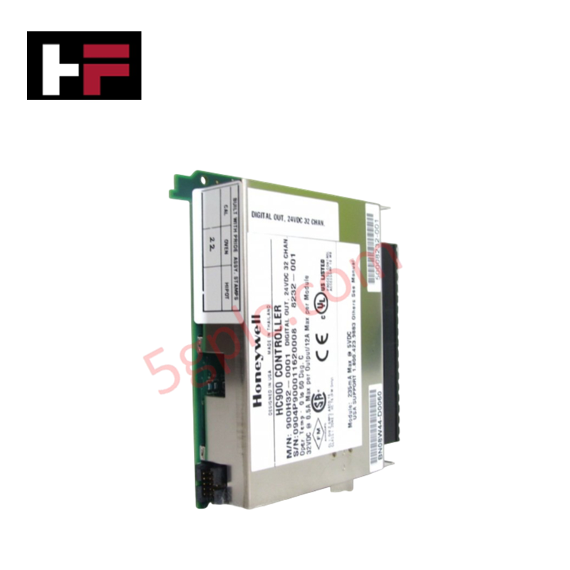
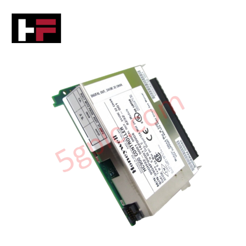
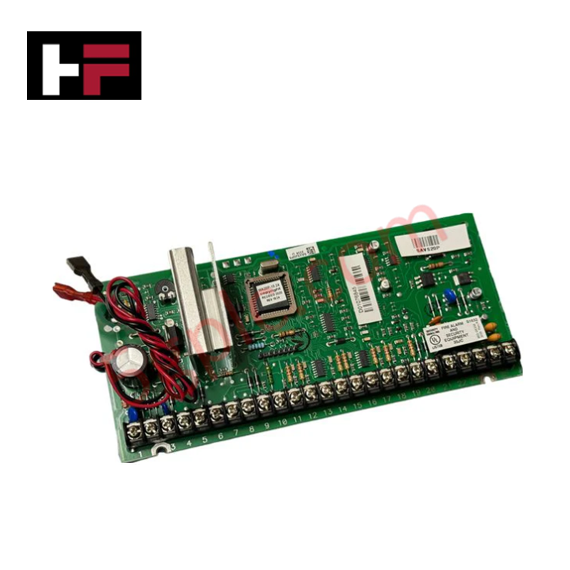
Configured for precision signal acquisition in IPC 620 control platforms, the Honeywell 621-0022 (621-0022 Analog Input Module) provides direct electrical execution for processing multi-range analog inputs. The hardware converts 4-20 mA current loops and 0-10 VDC voltage signals into digitized values for controller processing, maintaining circuit-level signal conditioning to ensure accurate data conversion across the host system.
Hardware Specifications
| Parameter | Specification |
|---|---|
| Model | 621-0022 |
| Brand | Honeywell |
| Weight | 0.68 kg |
| Dimensions | 127 x 127 x 127 mm |
| Input Type | 4-20 mA / 0-10 VDC |
| Signal Conversion | Analog to Digital |
Channel-to-Channel Isolation and Loop Integrity
The 621-0022 module utilizes channel-to-channel isolation to decouple field-side sensor loops from the internal system bus. This isolation barrier is intended to suppress common-mode noise and prevent ground loops from impacting the measurement accuracy of low-level analog signals. In multi-channel operation, users must ensure that external power supplies for active 4-20 mA devices are correctly referenced to prevent potential difference accumulation across the input terminals, which may otherwise compromise the linearity of the conversion process.
Frequently Asked Questions
Q: Can the input range be configured per channel for mixed 4-20 mA and 0-10 VDC signals?
A: Configuration is dependent on the specific revision of the module and the host system’s backplane addressing. Consult the controller I/O mapping documentation to verify if the physical hardware supports simultaneous heterogeneous input types.
Q: Is this module capable of providing loop power to passive 4-20 mA sensors?
A: The module's internal circuitry for loop excitation must be verified against the transmitter power requirements. If the transmitter is passive, an external 24 VDC power supply in series with the loop may be required.
Field Installation Guidelines
- Signal Wiring: Utilize shielded twisted-pair cabling for all analog input connections. Terminate the cable shield at a single designated chassis ground point to minimize EMI susceptibility.
- Backplane Engagement: Ensure the module is fully seated in the rack slot. Loose connections at the backplane interface may manifest as intermittent signal fluctuations or "floating" analog readings.
- Termination: When using 4-20 mA inputs, ensure that the current loop is completed through the module terminals. For 0-10 VDC inputs, ensure the source impedance is within the module's acceptable range to prevent signal attenuation.
- Physical Separation: Maintain a minimum distance of 15 cm between low-voltage analog signal cables and high-voltage power conduits to prevent inductive interference.
Additional Information
- 100% Genuine Parts: All products are original and authentic, ensuring reliable industrial performance.
- 30-Day Refund Guarantee: Return any in-stock item within 30 days in original, unopened packaging for a full refund (excluding shipping and fees).
- 12-Month Warranty: Covers defects in materials or workmanship; excludes misuse, normal wear, or unauthorized modifications.
- Worldwide Shipping: We ship via USPS, UPS, FedEx, and DHL. Delivery times vary by country and may be subject to customs or import fees.
- Support & Contact: Technical and warranty assistance is available anytime. Contact us here: Contact.
- Purchase Guidance: Check product specifications and compatibility carefully before ordering to ensure proper application.


Tech & Buying Guide

Redundant Automation Systems: Ensuring Continuous Uptime in Critical Control Infrastructure
System reliability directly determines operational profitability across high stakes process industries. Modern industrial automation platforms must eliminate single points of failure to prevent catastrophic shutdowns. Deploying fault tolerant architecture safeguards complex facilities against unexpected hardware glitches, network disruptions, and maintenance outages.

Understanding Types of Noise in Electronic Circuits and Control Systems
Signal integrity directly determines measurement accuracy and loop stability across industrial automation environments. Electronic noise introduces unwanted stochastic interference into analog loops, sensor feedback lines, and digital fieldbus networks. Understanding how intrinsic electronic noise and external electromagnetic interference manifest allows control engineers to optimize signal conditioning and shield sensitive instrumentation effectively.

Why 24V DC Power Supplies Standardize Modern Industrial Automation
Industrial control cabinets worldwide rely on 24V DC as the universal power standard for field instrumentation, sensors, and controllers. Walk into any manufacturing plant, and you will find PLCs, human-machine interfaces (HMIs), and smart actuators running on extra-low voltage DC. Standardizing on 24V DC enhances operational safety, lowers cabinet footprint, and maintains steady control performance across factory networks.