










Product Details
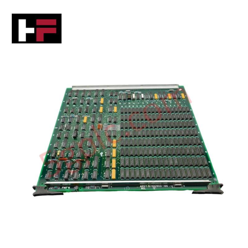
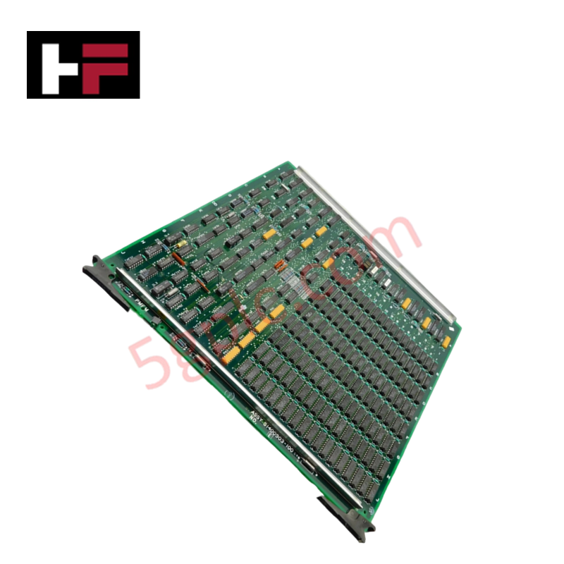
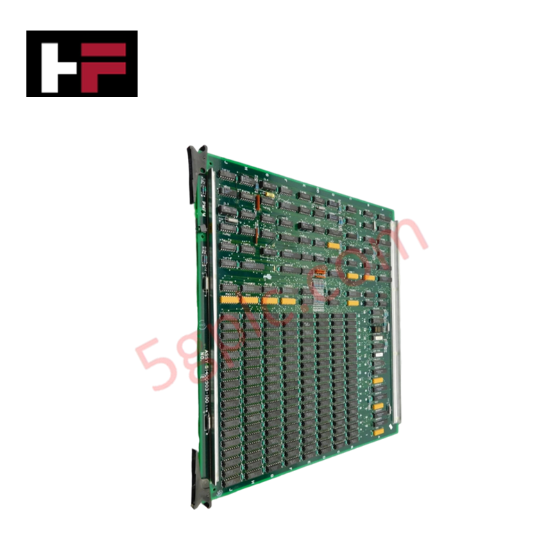
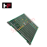
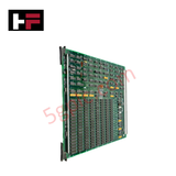
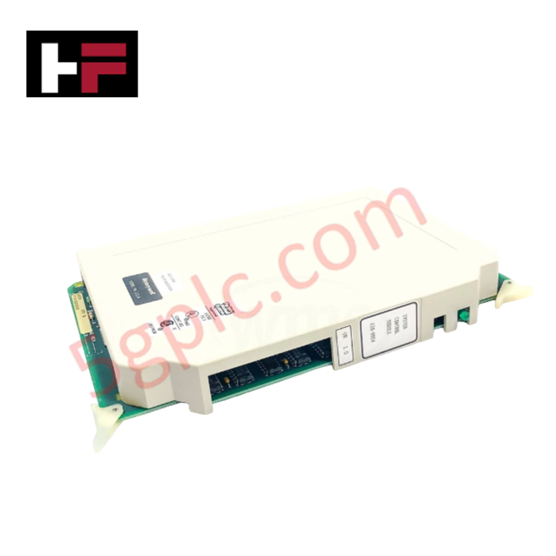
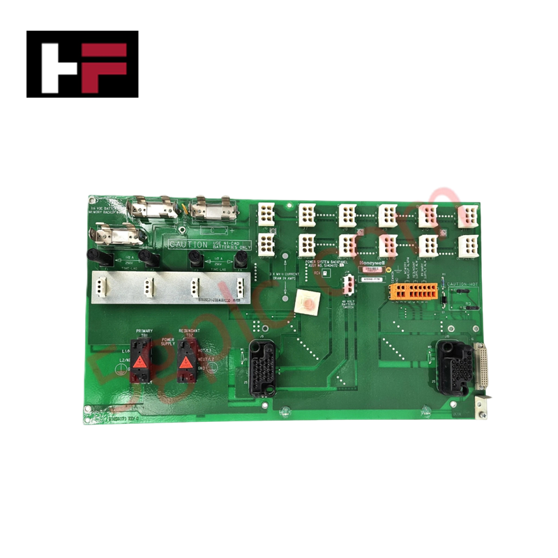
The Honeywell 51400903-100, also cataloged as the 51400903 Circuit Board, operates as a dedicated hardware component for internal system signal processing and logic execution within Honeywell TDC 3000 and Process Manager (PM/APM/HPM) DCS architectures.
Hardware Specifications
| Parameter | Specification |
|---|---|
| Model | 51400903-100 |
| Brand | Honeywell |
| Origin | USA |
| Weight | Approx. 0.8 kg |
| Operating Temp | 0 deg C to +60 deg C |
| Power Consumption | Powered via backplane bus (5 VDC / 24 VDC) |
| Module Type | Process Manager Circuit Board Assembly |
| System Compatibility | Honeywell TDC 3000 / PM / APM / HPM Card Cages |
| Form Factor | Single-slot printed circuit board |
4-20 mA HART Loop Protocol and Channel-to-Channel Isolation
Engineered for internal signal routing and data bus interfacing within Honeywell process control card cages, the assembly incorporates multi-layer ground planes and isolation barriers. Channel-to-channel isolation on onboard signal distribution paths suppresses common-mode electrical noise and prevents ground potential shifts from distorting low-level analog measurements or 4-20 mA HART loop protocol telemetry across field process interfaces.
Frequently Asked Questions
Q: What primary role does the 51400903-100 circuit board perform in a Honeywell DCS?
A: The board functions as an internal logic/interface printed circuit board assembly mounted within TDC 3000 Process Manager card cages to route and process system bus signals.
Q: Can the 51400903-100 circuit board be replaced while the card cage is powered?
A: Board removal or insertion should follow Honeywell system-specific hot-swap protocols; isolating power or placing the node in an offline state is recommended to prevent logic bus errors.
Q: How does the board maintain signal integrity in electrically noisy environments?
A: Onboard filtering, optocouplers, and dedicated ground planes provide galvanic isolation between field-side signals and internal high-speed backplane logic.
Field Installation Guidelines
- Handle the printed circuit board strictly by its front faceplate or frame, utilizing a wrist strap connected to cabinet protective earth (PE) to prevent electrostatic discharge (ESD) damage.
- Slide the board smoothly along the card cage guide rails until the rear edge-connector mates firmly with the backplane header.
- Tighten the top and bottom retaining screws to establish solid mechanical grounding to the rack chassis.
- Ensure proper cabinet ventilation and cooling fan operation to maintain ambient rack temperatures within specified limits.
Additional Information
- 100% Genuine Parts: All products are original and authentic, ensuring reliable industrial performance.
- 30-Day Refund Guarantee: Return any in-stock item within 30 days in original, unopened packaging for a full refund (excluding shipping and fees).
- 12-Month Warranty: Covers defects in materials or workmanship; excludes misuse, normal wear, or unauthorized modifications.
- Worldwide Shipping: We ship via USPS, UPS, FedEx, and DHL. Delivery times vary by country and may be subject to customs or import fees.
- Support & Contact: Technical and warranty assistance is available anytime. Contact us here: Contact.
- Purchase Guidance: Check product specifications and compatibility carefully before ordering to ensure proper application.

Tech & Buying Guide

Comprehensive Guide to Instrumentation and Control (I&C) Design Basis
Instrumentation and Control (I&C) Design Basis serves as the foundational technical document for modern plant engineering. Project teams rely on this master specification to govern engineering deliverables across front-end engineering design (FEED) and detailed execution phases. A well-constructed I&C design basis ensures seamless integration among field instrumentation, safety systems, and main control systems. Furthermore, establishing clear technical standards early mitigates execution risks and prevents costly re-engineering during plant commissioning.

The Shift to Flexible IO Modules in Modern Industrial Automation
Traditional control systems rely on dedicated Input Output (IO) cards for industrial automation. Each conventional module processes a single signal type, such as Digital Input (DI), Digital Output (DO), Analog Input (AI), or Analog Output (AO). A standard 16-channel card accepts only one specific channel type across all ports. This inflexible hardware design often creates severe engineering bottlenecks during project execution. Engineers frequently must install entirely new cards to accommodate a single extra sensor. Consequently, late design changes increase control cabinet space requirements and drive up project costs.

DCS Commissioning Steps in Industrial Automation Projects
Commissioning a Distributed Control System (DCS) represents a crucial milestone when deploying modern process automation infrastructure. Field engineers must execute systematic verification steps to transition complex control hardware from static installation to dynamic plant control. Proper commissioning ensures that controllers, I/O modules, network switches, and HMI software operate in strict compliance with engineering design specifications before introducing live process fluids.