










Product Details
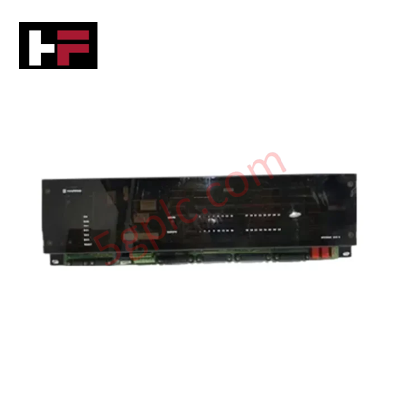
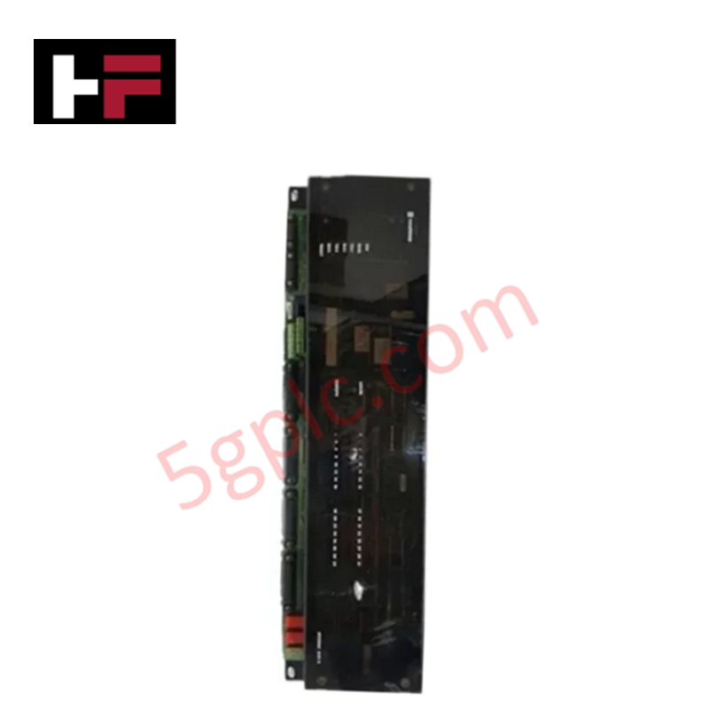
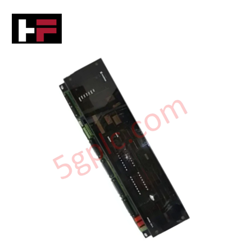
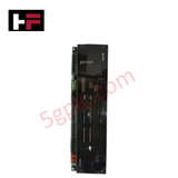
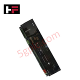
The GE WESDAC D10A, also cataloged as the WESDAC D10A Control Output Module, operates as a dedicated hardware component for multi-channel discrete actuation within GE Speedtronic Mark V control systems.
Hardware Specifications
| Parameter | Specification |
|---|---|
| Model | WESDAC D10A |
| Brand | GE |
| Origin | USA |
| Weight | 2.6 kg |
| Dimensions | 782 mm x 356 mm x 835 mm |
| Operating Temp | 0 - 60 deg C |
| Power Consumption | System Bus Dependent |
| Module Type | Control Output Module |
| Platform Series | Speedtronic Mark V |
| Output Configurations | Discrete relay contacts or semiconductor transistors |
| Mounting Base | DIN rail or internal panel mounting options |
Suffix Breakdown & Model Matrix
- WESDAC: Identifier indicating the core data acquisition and sub-component digital control platform family.
- D10A: Functional design version specifying the integrated multi-channel array layout, voltage threshold tolerances, and interface terminal spacing boundaries.
Profinet / EtherNet/IP Deterministic Networks and Driver Switching
The hardware converts internal system command register bytes into direct physical switching actions using an array of independent relay or transistor elements. While network interfaces across external controllers often interface via Profinet / EtherNet/IP deterministic networks, the native Mark V infrastructure routes data across localized internal bus tracks. Maintaining clear firmware flash compatibility between this output stage component and the host process controller is necessary to prevent command timing jitter or accidental state dropout anomalies.
Frequently Asked Questions
Q: Does the WESDAC D10A module support online hot-swapping while the system is energized?
A: No. The backplane and terminal interconnect paths are not designed with pre-charging isolation layers or delayed-pin grounding sequences. Extracting or seating this hardware under live control power will disrupt internal bus lines and may corrupt peripheral channel register states.
Q: How should different voltage loads be configured across the multi-channel terminal layout?
A: Channels must be segregated according to their specific output types (relays or transistors) and voltage ratings. Mixing alternating current (AC) lines and direct current (DC) logic paths on adjacent un-isolated channels can introduce capacitive crosstalk and compromise logic execution.
Field Installation Guidelines
- Structural Chassis Mounting: Anchor the module firmly to the DIN rail or backpanel alignment frame within the enclosure using standard hardware to eliminate physical vibration deflection.
- Discrete Routing Trajectories: Keep all high-current or inductive field wiring runs inside distinct wire trunking runs separated from low-voltage core communication lines to minimize electromagnetic cross-coupling.
- Terminal Interface Retention: Verify all screw clamp terminations are torqued down according to core standard guidelines to reduce contact resistance across active high-load relay junctions.
Additional Information
- 100% Genuine Parts: All products are original and authentic, ensuring reliable industrial performance.
- 30-Day Refund Guarantee: Return any in-stock item within 30 days in original, unopened packaging for a full refund (excluding shipping and fees).
- 12-Month Warranty: Covers defects in materials or workmanship; excludes misuse, normal wear, or unauthorized modifications.
- Worldwide Shipping: We ship via USPS, UPS, FedEx, and DHL. Delivery times vary by country and may be subject to customs or import fees.
- Support & Contact: Technical and warranty assistance is available anytime. Contact us here: Contact.
- Purchase Guidance: Check product specifications and compatibility carefully before ordering to ensure proper application.


Tech & Buying Guide

How to Connect to Siemens S7 PLCs: 5 Essential Communication Methods
Establishing a reliable hardware link between a programming terminal and a Siemens SIMATIC controller is essential for engineering workflows. Field engineers rely on distinct physical layers, ranging from legacy serial connections to high-speed Industrial Ethernet protocols. Modern factory automation environments prioritize fast data transfer and seamless driver integration. Selecting the correct connection method simplifies program downloads, online monitoring, and system troubleshooting in complex control systems.

Will PLCs Become Obsolete? The Future of Control Systems in Industry 4.0
Modern manufacturing is undergoing a rapid technological transformation driven by Industry 4.0 innovations. Technologies like Artificial Intelligence (AI), Machine Learning (ML), and the Industrial Internet of Things (IIoT) are dominating discussions across the factory automation sector. Consequently, many engineers wonder if these advanced digital tools will eventually replace traditional Programmable Logic Controllers (PLCs). However, evaluating the core physics of industrial operations reveals a very different reality for control systems.

Demystifying Open Platform Communication (OPC): The Backbone of Industrial Interoperability
Interoperability remains a cornerstone requirement for modern smart factories and process automation. Open Platform Communication (OPC) bridges the gap between disparate hardware platforms, control systems, and visualization software. By establishing a universal communication standard, OPC allows field controllers, SCADA platforms, and enterprise software from different vendors to exchange real-time data seamlessly.