










Product Details
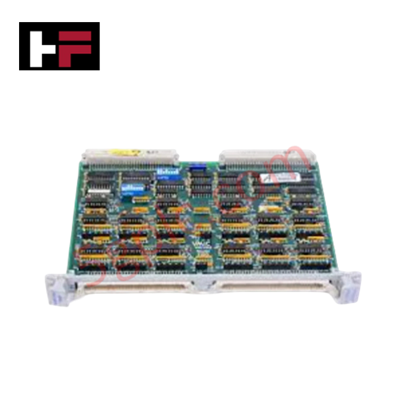
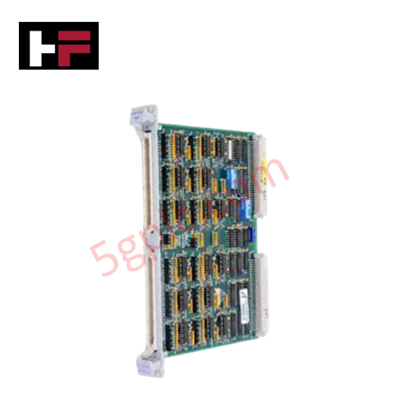
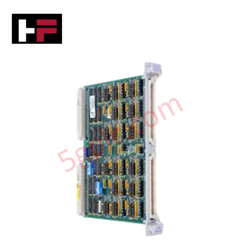
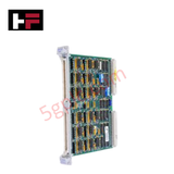
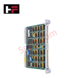
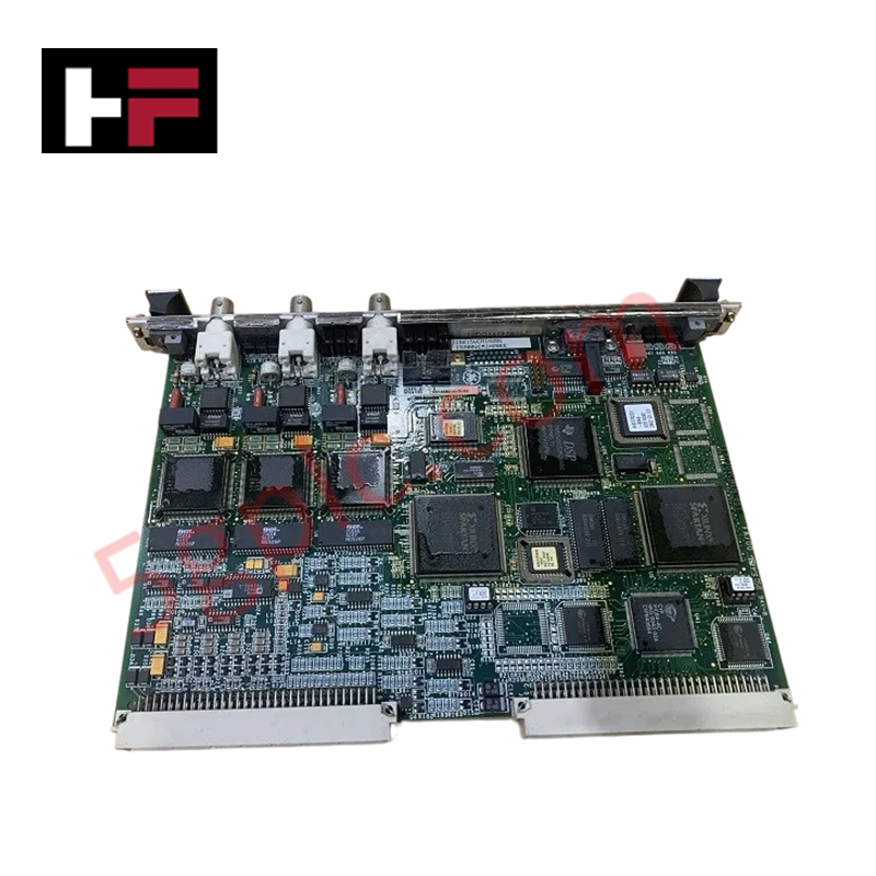
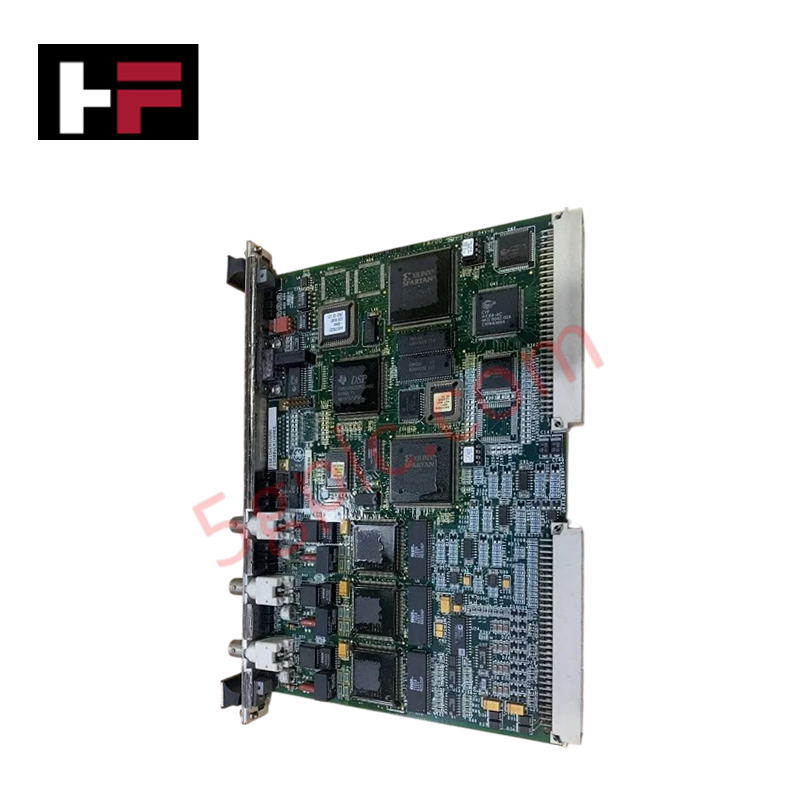
The GE VMIVME-1150 332-001150-120, also cataloged as the VMIVME-1150 Digital Input Board, operates as a dedicated hardware component for processing discrete voltage states within VMEbus architecture networks.
Hardware Specifications
| Parameter | Specification |
|---|---|
| Model | VMIVME-1150 332-001150-120 |
| Brand | GE Fanuc |
| Origin | United States |
| Weight | 0.52 kg |
| Dimensions | 483 mm x 203 mm x 279 mm |
| Operating Temp | 0 - 55 deg C |
| Power Consumption | VMEbus Backplane Dependent |
| Input Channels | 64 optically isolated channels |
| Input Voltage Range | 5 - 48 VDC |
| Isolation Type | Optocoupler |
| Form Factor | VME Double Eurocard |
I/O Density Scaling and Backplane Bus Communications
The hardware employs a 64-channel array to achieve high-density scaling within a VME double Eurocard framework. Discrete field signal registers are polled concurrently and written directly to the backplane bus interface. To prevent signal bounce from generating invalid logic states during high-velocity data transfers, the module incorporates optocoupler circuits that decouple the 5 - 48 VDC field loops from the TTL logic lines of the processing rack.
Frequently Asked Questions
Q: Does the VMIVME-1150 332-001150-120 support hot-swapping or live insertion?
A: No. The parallel VMEbus architecture used on this board does not feature staggered power pins. Inserting or pulling the card while the backplane bus is energized will cause voltage transients that can corrupt data or destroy the bus drivers.
Q: How can the input channels be configured for different field sensors?
A: The board layout supports flexible circuit setups, allowing channels to be wired for contact closure sensing, voltage sourcing, or current sinking operations by adjusting external field wiring jumpers.
Field Installation Guidelines
- Mechanical Seat Verification: Insert the module into the designated slot guides of the VME chassis. Depress the dual injector/ejector handles simultaneously to ensure full pin alignment with the backplane connectors before tightening the panel screws.
- Field Cable Isolation: Route all 5 - 48 VDC input wiring paths through distinct, separate wire ways away from high-power alternating current (AC) lines or variable frequency drive cables to suppress electromagnetic noise.
- Shielding Ground Continuity: Connect external signal line shields to a centralized, unpainted enclosure ground bar. Do not ground the cable shield at both ends to prevent creating problematic ground loop currents.
Additional Information
- 100% Genuine Parts: All products are original and authentic, ensuring reliable industrial performance.
- 30-Day Refund Guarantee: Return any in-stock item within 30 days in original, unopened packaging for a full refund (excluding shipping and fees).
- 12-Month Warranty: Covers defects in materials or workmanship; excludes misuse, normal wear, or unauthorized modifications.
- Worldwide Shipping: We ship via USPS, UPS, FedEx, and DHL. Delivery times vary by country and may be subject to customs or import fees.
- Support & Contact: Technical and warranty assistance is available anytime. Contact us here: Contact.
- Purchase Guidance: Check product specifications and compatibility carefully before ordering to ensure proper application.
Tech & Buying Guide

Transforming Shop Floor Data into Actionable Insights: A Deep Dive into MES
Manufacturing Execution Systems serve as the digital backbone of modern factory floors. Positioned at Level 3 of the ISA-95 automation pyramid, MES links enterprise resource planning with real-time shop floor control systems. Today, industrial operators rely on MES software to bridge operational strategy with physical production execution.

Managed Switch vs. Unmanaged Switch: Industrial Ethernet Architecture

Hot Standby vs. Cold Standby Redundancy in Industrial Automation
System availability determines process safety and productivity in industrial automation. Control engineers deploy redundancy to eliminate single points of failure. This technical guide evaluates Hot Standby vs. Cold Standby architectures, comparing failover speeds, memory sync, cost trade-offs, and field selection criteria.