


Product Details
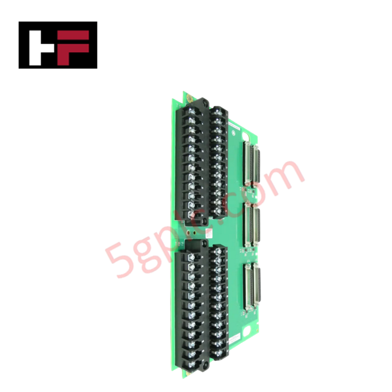
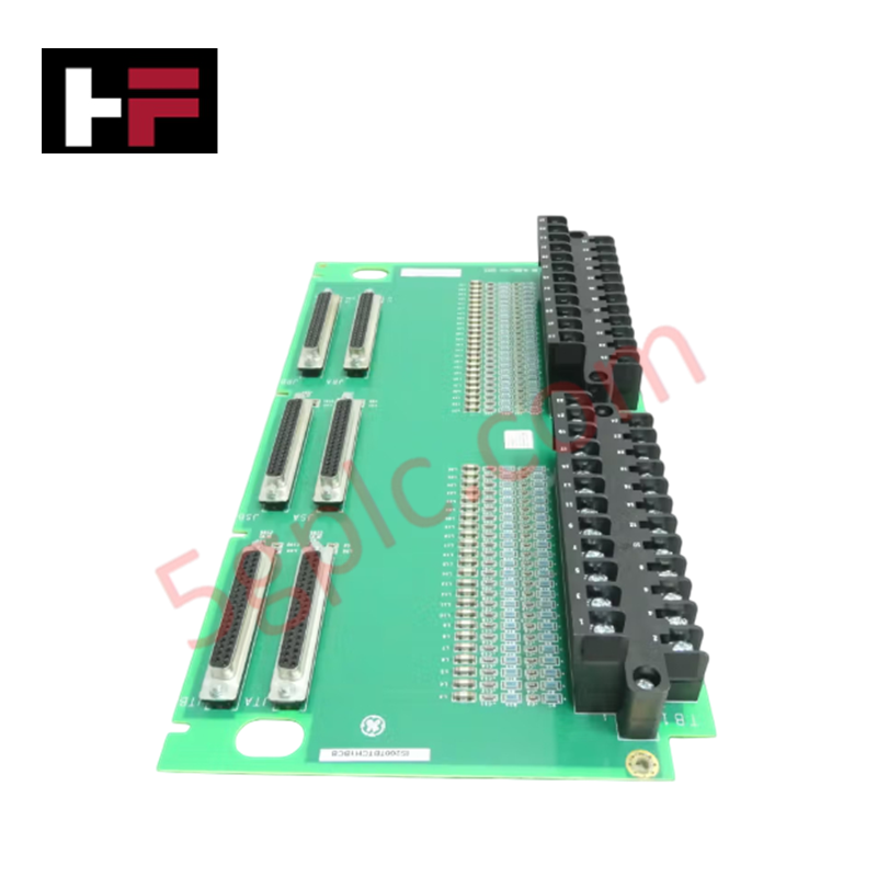
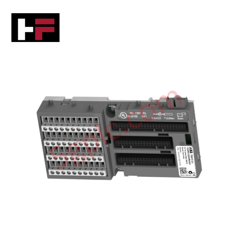
Configured for signal termination in Mark VI Speedtronic turbine control systems, the GE IS200TBTCH1B (IS200TBTCH1B Thermocouple Input Terminal Board) provides direct physical execution of thermocouple signal routing. This hardware component serves as the primary TBTC terminal board utilized to execute precise sensor interface connections across Mark VI platform architectures.
Hardware Specifications
| Parameter | Specification |
|---|---|
| Model | IS200TBTCH1B |
| Brand | GE |
| Dimensions | Standard PCB form factor |
| Operating Temp | Standard industrial ambient range |
| Power Consumption | Passive signal routing |
| Core Performance | Thermocouple signal termination; conformal coated |
Backplane Bus Communication and Deterministic Networks
The IS200TBTCH1B functions as a signal interface board, facilitating the connection between field-mounted thermocouple sensors and the Mark VI I/O processor modules. The board is treated with a conformal coating to protect the surface-mount components from humidity, dust, and corrosive airborne contaminants typical of industrial turbine environments. As a terminal board, it does not actively manage backplane bus communication velocity; rather, it ensures signal integrity for the connected I/O processor. Firmware flash compatibility is governed by the host I/O pack, which performs the cold junction compensation (CJC) calculations based on the signals routed through this terminal board. Deterministic I/O density scaling is achieved by utilizing multiple TBTC boards to increase the total number of monitored thermocouple points within a single control cabinet.
Frequently Asked Questions
Q: Is this terminal board active or passive?
A: The IS200TBTCH1B is a passive terminal board. It provides mechanical connectivity for field wiring and routes signals to the I/O processor; it contains no active logic or processing components.
Q: Can this board be used with RTD sensors?
A: No. The terminal board is specifically designed for thermocouple inputs. RTD sensors require different input scaling and signal processing logic, which would result in inaccurate data if connected to a TBTC board.
Field Installation Guidelines
- Mounting: Secure the PCB in the designated Mark VI cabinet location. Ensure the board is properly grounded to the cabinet chassis through the provided mounting points to minimize electromagnetic interference.
- Wiring: Use thermocouple extension wire that matches the sensor type (e.g., Type K, Type J). Maintain consistent polarity throughout the wiring run to the terminal block to prevent measurement errors.
- Shielding: Terminate cable shields at the designated common ground bus bar within the cabinet. Ensure the shield is not connected at the sensor end if the installation environment is prone to ground loops.
- Inspection: Regularly inspect the terminal connections for oxidation or mechanical fatigue, especially in high-vibration areas. Use a calibrated torque driver to secure connections according to specification to maintain low-resistance signal paths.
Additional Information
- 100% Genuine Parts: All products are original and authentic, ensuring reliable industrial performance.
- 30-Day Refund Guarantee: Return any in-stock item within 30 days in original, unopened packaging for a full refund (excluding shipping and fees).
- 12-Month Warranty: Covers defects in materials or workmanship; excludes misuse, normal wear, or unauthorized modifications.
- Worldwide Shipping: We ship via USPS, UPS, FedEx, and DHL. Delivery times vary by country and may be subject to customs or import fees.
- Support & Contact: Technical and warranty assistance is available anytime. Contact us here: Contact.
- Purchase Guidance: Check product specifications and compatibility carefully before ordering to ensure proper application.
Tech & Buying Guide

Mastering the Factory Acceptance Test (FAT) for PLC Control Panels: An Expert Guide
The Factory Acceptance Test (FAT) is a vital milestone in industrial automation that ensures custom PLC panels meet exact design specifications before dispatch. This guide outlines the step-by-step FAT procedure and key industry best practices to prevent costly site delays and ensure long-term operational success.

Redundant Automation Systems: Ensuring Continuous Uptime in Critical Control Infrastructure
System reliability directly determines operational profitability across high stakes process industries. Modern industrial automation platforms must eliminate single points of failure to prevent catastrophic shutdowns. Deploying fault tolerant architecture safeguards complex facilities against unexpected hardware glitches, network disruptions, and maintenance outages.

Understanding Types of Noise in Electronic Circuits and Control Systems
Signal integrity directly determines measurement accuracy and loop stability across industrial automation environments. Electronic noise introduces unwanted stochastic interference into analog loops, sensor feedback lines, and digital fieldbus networks. Understanding how intrinsic electronic noise and external electromagnetic interference manifest allows control engineers to optimize signal conditioning and shield sensitive instrumentation effectively.