Product Details
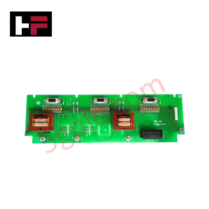
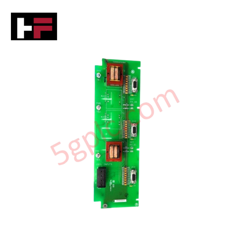
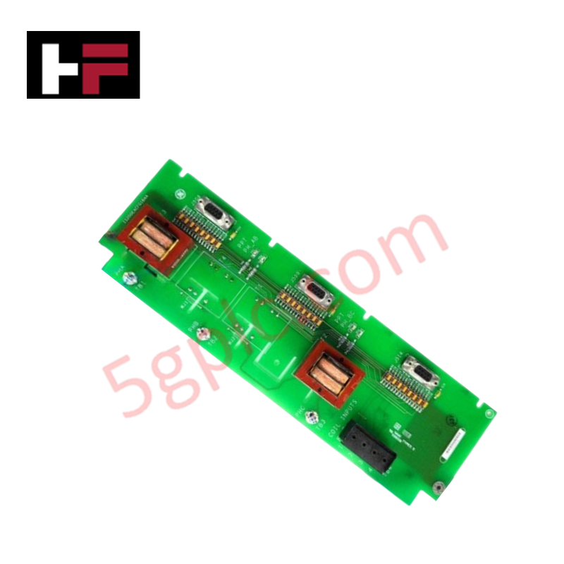
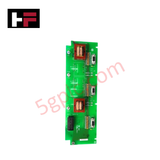
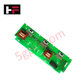
Configured for exciter supply monitoring in EX2100 Excitation Control platforms, the GE IS200EACFG1B (IS200EACFG1B AC Feedback Board) provides direct physical/electrical execution of AC voltage and current measurement.
Hardware Specifications
| Parameter | Specification |
|---|---|
| Model | IS200EACFG1B |
| Brand | General Electric |
| Origin | USA |
| Measurement Inputs | Exciter PPT AC supply voltage and current |
Backplane Bus Communication Velocity and Firmware Compatibility
The IS200EACFG1B functions as a signal acquisition interface within the EX2100 control architecture. It samples phase voltage outputs derived from potential transformers and maps them to internal system registers. Deterministic communication via the backplane bus ensures that the voltage feedback data is processed in phase with control loop requirements. Firmware flash compatibility is managed through the master controller, allowing for calibration adjustments of the voltage measurement scaling to account for varying potential transformer ratios within the exciter system.
Frequently Asked Questions
Q: How are the potential transformer (PT) voltage inputs verified on the board?
A: Verification is performed via voltage test rings TP1 through TP4. Phase-to-phase voltage AB is measured between TP1 and TP2, BC between TP3 and TP4, and CA between TP4 and TP1. Ensure high-impedance measurement instrumentation is utilized to avoid loading the PT secondary circuits.
Q: Can this board be replaced without recalibrating the excitation control loops?
A: Given that the board serves as an analog feedback interface, any physical replacement requires verification of the voltage feedback scaling within the EX2100 configuration software to ensure measured values correlate with actual primary side inputs.
Field Installation Guidelines
- Pre-Installation Inspection: Inspect the board for physical damage to the test rings and edge connectors. Ensure that the PCB surface is free of conductive dust or contaminants that could cause flashover at the PT input voltages.
- Signal Wiring: PT secondary wiring must be routed to avoid proximity to high-current output cables. Maintain consistent phase orientation during termination at the board inputs to prevent phase-shift errors in the feedback logic.
- Grounding: The PCB must be securely seated in the designated EX2100 rack slot to ensure proper connection to the chassis ground plane. This is required for the stability of the analog-to-digital measurement reference.
- Maintenance: Periodically check for tightness of terminal connections to prevent high-resistance contact points, which can introduce thermal noise and degrade the signal-to-noise ratio of the AC feedback measurements.
Additional Information
- 100% Genuine Parts: All products are original and authentic, ensuring reliable industrial performance.
- 30-Day Refund Guarantee: Return any in-stock item within 30 days in original, unopened packaging for a full refund (excluding shipping and fees).
- 12-Month Warranty: Covers defects in materials or workmanship; excludes misuse, normal wear, or unauthorized modifications.
- Worldwide Shipping: We ship via USPS, UPS, FedEx, and DHL. Delivery times vary by country and may be subject to customs or import fees.
- Support & Contact: Technical and warranty assistance is available anytime. Contact us here: Contact.
- Purchase Guidance: Check product specifications and compatibility carefully before ordering to ensure proper application.


Tech & Buying Guide

Voice-Activated Industrial Automation: Integrating Speech Control into PLC and DCS Architectures
Industrial automation integrates speech recognition, IIoT protocols, and NLP with PLCs and DCS to streamline operations. By leveraging advanced edge computing, engineers enable real-time, hands-free control—allowing personnel to manage smart factory processes safely away from hazardous equipment.
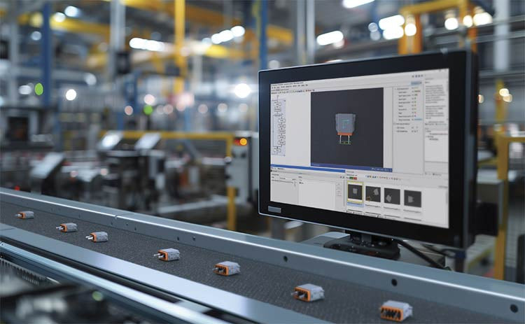
Modern Industrial Automation: Transforming Safety and Efficiency in Mining Operations
Industrial automation has evolved from a simple manufacturing tool into the operational backbone of high-risk sectors. Modern mining operations increasingly rely on advanced control systems, programmable logic controllers (PLCs), distributed control systems (DCS), and artificial intelligence to address deep-underground hazards. By replacing manual labor in high-risk zones, factory automation technologies protect personnel while significantly boosting operational throughput.