











Product Details
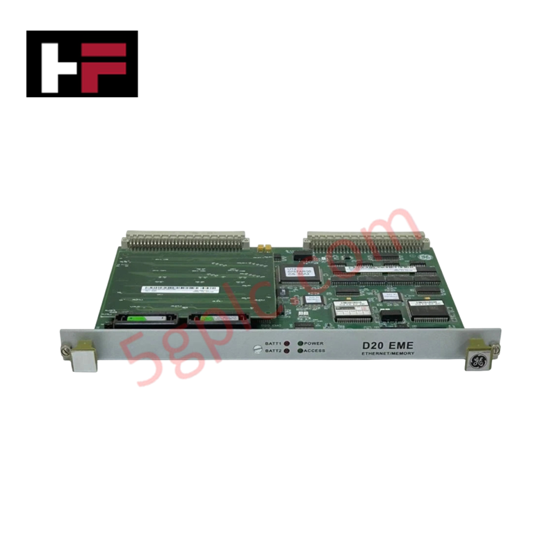
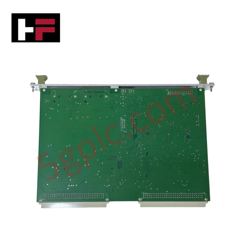
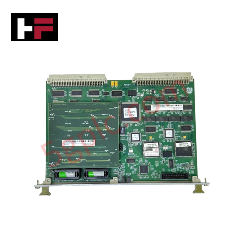
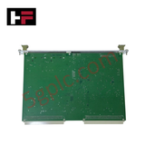
Configured for high-speed Ethernet communication and memory expansion in GE Fanuc control platforms, the GE Fanuc 820-0757 (820-0757 Ethernet & Memory Expansion Module) provides direct physical/electrical execution.
Hardware Specifications
| Parameter | Specification |
|---|---|
| Model | 820-0757 |
| Brand | GE Fanuc |
| Origin | USA |
| Module Type | Ethernet & Memory Expansion Module |
| Dimensions | 100 mm x 80 mm x 20 mm |
| Weight | 0.57 kg |
| Operating Temp | -40 to +70 deg C |
| Power Consumption | Rack backplane bus dependent |
| Protocol Support | Modbus TCP/IP |
| Physical Media | 10/100 Mbps RJ45 twisted-pair interface |
| Enclosure Protection | Rugged industrial panel mount |
Backplane Bus Communication & Firmware Flash Compatibility
The expansion module integrates directly into the local backplane architecture, expanding physical onboard RAM and Flash reserves to execute edge diagnostics and complex data logging routines. Internal firmware flash compatibility facilitates deterministic packet processing across Modbus TCP/IP networks without introducing latency to internal controller task execution. High-bandwidth backplane bus communication velocity allows simultaneous real-time data streaming and system memory indexing across operating temperature extremes.
Frequently Asked Questions
Q: How does the module interface with the main controller backplane?
A: The board mounts directly into the backplane expansion interface, drawing operational logic power and establishing high-speed parallel bus lines for memory addressing.
Q: What network protocols are handled natively by the onboard communication hardware?
A: The module natively executes Modbus TCP/IP protocol stacks over industrial Ethernet channels for deterministic data exchange with SCADA nodes and PLC units.
Q: What environmental tolerances are supported for harsh panel installations?
A: The hardware is rated for continuous operation across an extended temperature range of -40 to +70 deg C, with mechanical shock and vibration damping built into the housing profile.
Field Installation Guidelines
- Power down the host chassis or backplane assembly before inserting the expansion board into its designated panel slot.
- Align the module housing with the mounting guides and push until the rear backplane edge connectors mate fully.
- Secure the front panel retaining hardware to maintain protective chassis earthing and prevent vibration-induced loosening.
- Route Category 5e/6 shielded twisted-pair Ethernet cabling away from high-voltage motor conductors or variable frequency drive cables.
- Connect cable shielding to the panel master ground bus at a single point to prevent circulating earth potential currents.
Additional Information
- 100% Genuine Parts: All products are original and authentic, ensuring reliable industrial performance.
- 30-Day Refund Guarantee: Return any in-stock item within 30 days in original, unopened packaging for a full refund (excluding shipping and fees).
- 12-Month Warranty: Covers defects in materials or workmanship; excludes misuse, normal wear, or unauthorized modifications.
- Worldwide Shipping: We ship via USPS, UPS, FedEx, and DHL. Delivery times vary by country and may be subject to customs or import fees.
- Support & Contact: Technical and warranty assistance is available anytime. Contact us here: Contact.
- Purchase Guidance: Check product specifications and compatibility carefully before ordering to ensure proper application.


Tech & Buying Guide

Mastering the Siemens PLC Scan Cycle: How the CPU Executes Automation Programs
Industrial automation relies heavily on programmable logic controllers (PLCs) to manage complex manufacturing processes. Many engineers dive straight into programming without mastering the underlying architecture. However, understanding how a PLC CPU executes a program ensures reliable system design. Therefore, mastering the scan cycle optimizes both performance and troubleshooting in modern control systems.

How to Connect to Siemens S7 PLCs: 5 Essential Communication Methods
Establishing a reliable hardware link between a programming terminal and a Siemens SIMATIC controller is essential for engineering workflows. Field engineers rely on distinct physical layers, ranging from legacy serial connections to high-speed Industrial Ethernet protocols. Modern factory automation environments prioritize fast data transfer and seamless driver integration. Selecting the correct connection method simplifies program downloads, online monitoring, and system troubleshooting in complex control systems.

Will PLCs Become Obsolete? The Future of Control Systems in Industry 4.0
Modern manufacturing is undergoing a rapid technological transformation driven by Industry 4.0 innovations. Technologies like Artificial Intelligence (AI), Machine Learning (ML), and the Industrial Internet of Things (IIoT) are dominating discussions across the factory automation sector. Consequently, many engineers wonder if these advanced digital tools will eventually replace traditional Programmable Logic Controllers (PLCs). However, evaluating the core physics of industrial operations reveals a very different reality for control systems.