


Product Details
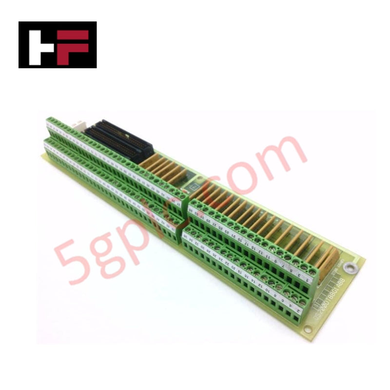
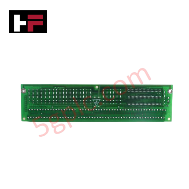
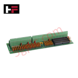
Configured for high-density signal termination within Mark V drive systems, the GE DS200DTBBG1A (DS200DTBB Terminal Board) provides direct physical execution of digital I/O interfacing.
Hardware Specifications
| Parameter | Specification |
|---|---|
| Model | DS200DTBBG1A |
| Brand | GE |
| Core Performance | 2 terminal blocks, 3 40-pin connectors, 5 jumpers |
Industrial Control & Drive Integration
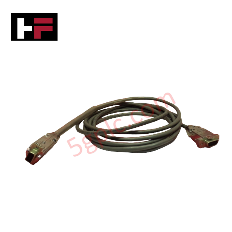
The DS200DTBBG1A facilitates I/O density scaling by providing centralized termination points for digital signal wires across the Mark V platform. The board interfaces with the drive control system via three 40-pin ribbon cable connectors (JFF, JFG, JFH). Effective system synchronization depends on precise firmware flash compatibility and adherence to terminal mapping (TB1-TB2). While the board lacks internal active processing logic, its performance is contingent on backplane bus communication velocity maintained by the host drive processor. The physical layout supports up to 110 total signal connections, requiring strict documentation of cable routing to ensure deterministic I/O signal path integrity.
Frequently Asked Questions
Q: Does this board support hot-swapping for maintenance?
A: No. The DS200DTBBG1A must be serviced only when the drive system is de-energized and locked out. Removing or installing ribbon cables while the drive is active can result in signal transients and potential damage to the control system I/O processors.
Q: How should I manage the 40-pin ribbon cable connections?
A: Each cable must be mapped to its corresponding connector (JFF, JFG, JFH). Improper connection will prevent the drive from recognizing the digital I/O signals, requiring a full system shutdown and manual cable reassignment to restore operation.
Q: Are there any user-configurable settings on the board?
A: The board includes five physical jumpers. These are set to align the board's electrical state with the specific drive configuration. Ensure jumper positions are verified against site-specific documentation before installation.
Field Installation Guidelines
- Terminal Mapping: Identify signal terminations using the TB1 and TB2 designations followed by the specific terminal number (e.g., TB1-90). Use wire markers to track all 110 potential connections.
- Ribbon Cable Seating: Ensure 40-pin connectors are fully seated on the JFF, JFG, and JFH headers. Verify that cables are free from mechanical tension and routed away from high-voltage AC paths to prevent electromagnetic interference.
- Torque Specifications: When securing signal wires to TB1 or TB2, ensure terminal screws are tightened to the specified torque to prevent loose connections or oxidation-induced high-resistance faults.
- Inspection: Prior to energizing, inspect the board for debris and verify that no stray strands of wire have bridged adjacent terminal contacts.
Additional Information
- 100% Genuine Parts: All products are original and authentic, ensuring reliable industrial performance.
- 30-Day Refund Guarantee: Return any in-stock item within 30 days in original, unopened packaging for a full refund (excluding shipping and fees).
- 12-Month Warranty: Covers defects in materials or workmanship; excludes misuse, normal wear, or unauthorized modifications.
- Worldwide Shipping: We ship via USPS, UPS, FedEx, and DHL. Delivery times vary by country and may be subject to customs or import fees.
- Support & Contact: Technical and warranty assistance is available anytime. Contact us here: Contact.
- Purchase Guidance: Check product specifications and compatibility carefully before ordering to ensure proper application.


Tech & Buying Guide

Redundant Automation Systems: Ensuring Continuous Uptime in Critical Control Infrastructure
System reliability directly determines operational profitability across high stakes process industries. Modern industrial automation platforms must eliminate single points of failure to prevent catastrophic shutdowns. Deploying fault tolerant architecture safeguards complex facilities against unexpected hardware glitches, network disruptions, and maintenance outages.

Understanding Types of Noise in Electronic Circuits and Control Systems
Signal integrity directly determines measurement accuracy and loop stability across industrial automation environments. Electronic noise introduces unwanted stochastic interference into analog loops, sensor feedback lines, and digital fieldbus networks. Understanding how intrinsic electronic noise and external electromagnetic interference manifest allows control engineers to optimize signal conditioning and shield sensitive instrumentation effectively.

Why 24V DC Power Supplies Standardize Modern Industrial Automation
Industrial control cabinets worldwide rely on 24V DC as the universal power standard for field instrumentation, sensors, and controllers. Walk into any manufacturing plant, and you will find PLCs, human-machine interfaces (HMIs), and smart actuators running on extra-low voltage DC. Standardizing on 24V DC enhances operational safety, lowers cabinet footprint, and maintains steady control performance across factory networks.