










Product Details
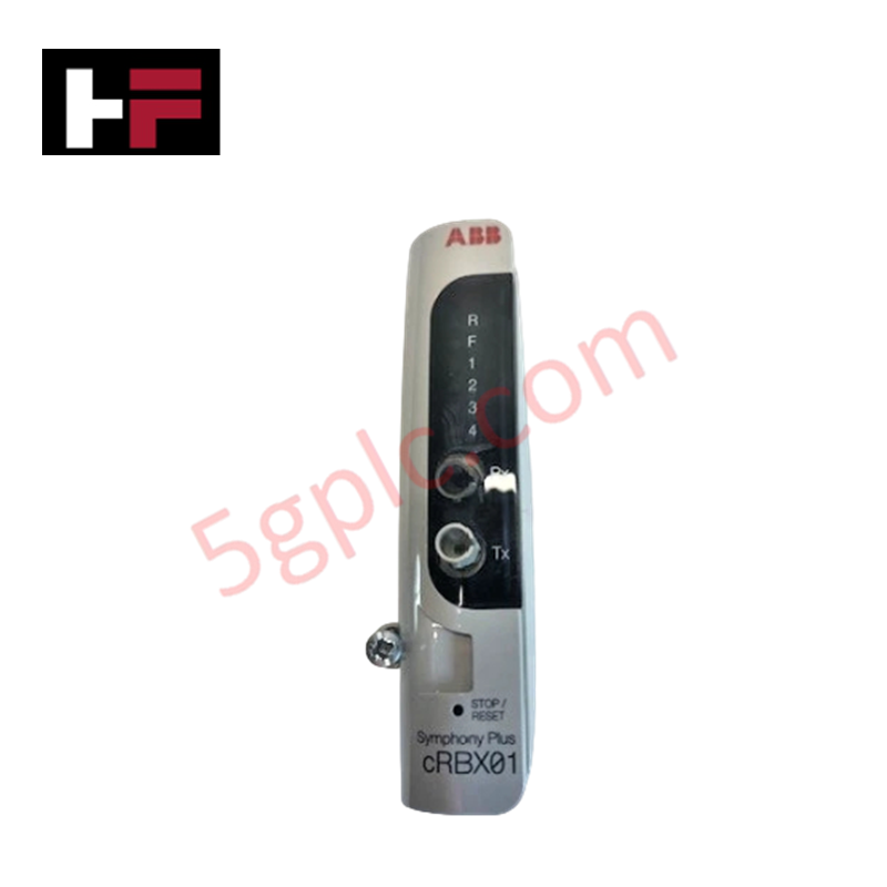
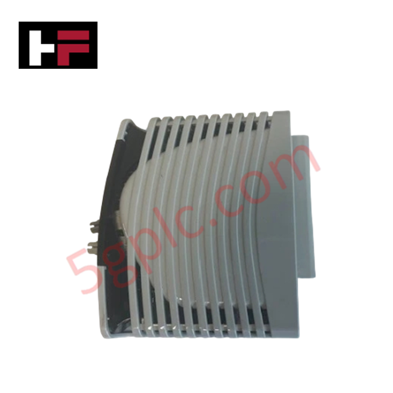
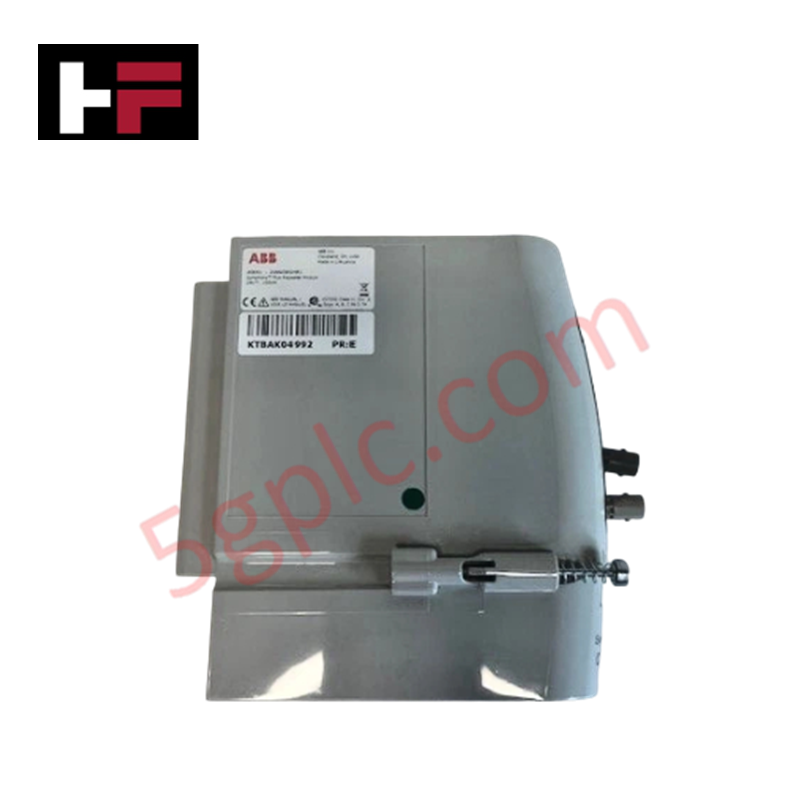
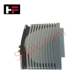
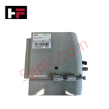
The ABB 2VAA008424R1, also cataloged as the cRBX01 Communication Module, operates as a dedicated hardware component for fiber optic signal repetition within remote bus extension topologies.
Hardware Specifications
| Parameter | Specification |
|---|---|
| Model | cRBX01 2VAA008424R1 |
| Brand | ABB |
| Origin | Sweden / Germany |
| Weight | 0.166 kg |
| Dimensions | 34 mm (Width) x 127 mm (Height) x 128 mm (Depth) |
| Operating Temp | -20 to +60 deg C (Standard industrial parameters) |
| Power Consumption | Sourced via local system chassis backplane bus |
| Functionality | Fiber optic repeater for remote bus network extension |
| Analog Input Channels | 0 |
| Analog Output Channels | 0 |
| HS Code | 85176200 |
| Environmental Compliance | RoHS compliant (EU Directive 2011/65/EU) |
| WEEE Category | 5. Small Equipment (No external dimension more than 50 cm) |
Profinet / EtherNet/IP Deterministic Networks and I/O Density Scaling
The device functions as a physical-layer optical transceiver that re-clocks and amplifies data packets transferred over long-distance serial control links. By using dedicated internal optoelectronic arrays, the hardware maintains the native backplane bus communication velocity across segmented racks. This setup allows flexible I/O density scaling options across remote nodes while preserving synchronization with primary Profinet or EtherNet/IP deterministic networks, preventing data signal degradation and ensuring precise firmware flash compatibility across network nodes.
Frequently Asked Questions
Q: Does the cRBX01 communication module require independent software addressing on the network?
A: No. The cRBX01 operates primarily as a physical-layer fiber optic repeater. It does not occupy a logical node address in the application firmware, allowing transparent transmission of data packets across the remote bus extension path.
Q: What are the backplane constraints when extracting the module under live power conditions?
A: Hot-swapping capabilities depend on the specific hosting rack chassis specification. To prevent data corruption on remote sub-racks, the active network traffic must be rerouted or the linked communication channels put in a safe state before physical module extraction.
Field Installation Guidelines
- Chassis Engagement: Insert the module into the designated slot on the DIN-rail assembly or backplane baseplate. Push firmly until the module connector engages completely with the terminal alignment blocks.
- Fiber Optic Handling: Clean all optical fiber connector ferrules prior to insertion into the transceiver ports. Maintain the minimum specified bend radius for fiber optic cables inside the control enclosure to prevent signal attenuation.
- Grounding Protocol: Ensure the metal grounding clip on the module housing establishes a low-impedance connection with the cabinet structural steel frame to ensure effective electromagnetic immunity.
Additional Information
- 100% Genuine Parts: All products are original and authentic, ensuring reliable industrial performance.
- 30-Day Refund Guarantee: Return any in-stock item within 30 days in original, unopened packaging for a full refund (excluding shipping and fees).
- 12-Month Warranty: Covers defects in materials or workmanship; excludes misuse, normal wear, or unauthorized modifications.
- Worldwide Shipping: We ship via USPS, UPS, FedEx, and DHL. Delivery times vary by country and may be subject to customs or import fees.
- Support & Contact: Technical and warranty assistance is available anytime. Contact us here: Contact.
- Purchase Guidance: Check product specifications and compatibility carefully before ordering to ensure proper application.
Tech & Buying Guide

Understanding Remote Terminal Units: The Core of SCADA and Telemetry Systems

Ultimate Guide to Schneider Electric PLCs: Selecting Control Systems for Small to Medium Automation
Schneider Electric remains a dominant force in global industrial automation, delivering robust control systems across diverse sectors. For control engineers, selecting the right programmable logic controller (PLC) requires balancing budget, communication ports, and processing power. This technical breakdown explores Schneider’s small and medium portfolio, offering field-tested insights to help you optimize your next factory automation project.

Essential Maintenance Guide for PLC, DCS, and ESD Marshalling Cabinets
Marshalling cabinets serve as the vital interface between field instrumentation and your core control systems. In large-scale industrial automation, these panels house the intricate wiring for PLC, DCS, and Emergency Shutdown (ESD) systems. Regular, systematic health checks are non-negotiable to ensure operational reliability and prevent costly unplanned downtime.