








Product Details
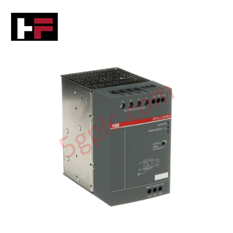
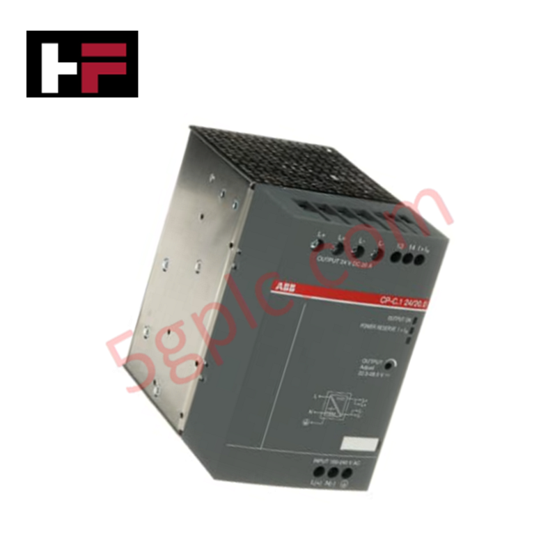
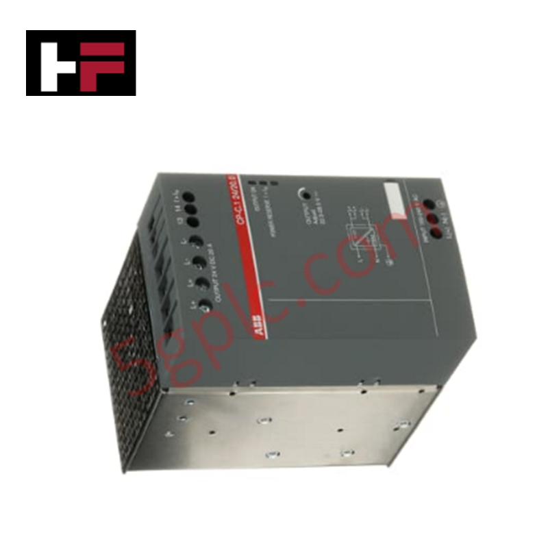
The ABB CP-C.1 24/20.0 1SVR360763R1001, also cataloged as the CP-C.1 24/20.0 Switch Mode Power Supply, operates as a dedicated hardware component for direct current voltage conversion and power delivery within industrial automation cabinets. The module transforms wide-range AC or DC input voltages into a regulated 24 VDC bus supply, providing power reserves for control electronics, PLC racks, and field instrumentation.
Hardware Specifications
| Parameter | Specification |
|---|---|
| Model | CP-C.1 24/20.0 1SVR360763R1001 |
| Brand | ABB |
| Origin | Germany |
| Weight | Standard DIN-rail module weight |
| Dimensions | Enclosure for TH35 DIN-rail mounting |
| Operating Temp | -25 to +70 deg C (Storage: -40 to +85 deg C) |
| Power Consumption | Input Current: 4.6 A at 115 VAC / 2.3 A at 230 VAC |
| Input Voltage | 85 ... 264 VAC / 90 ... 300 VDC |
| Output Voltage | 24 VDC adjustable (22.5 ... 28.5 VDC) |
| Output Current | 20 A continuous (26 A reserve at -25 to +40 deg C) |
| Rated Output Power | 480 W |
| Protection Rating | IP20 (Housing and Terminals) |
Backplane Bus Communication Velocity and Firmware Flash Compatibility
Although operating primarily as an independent power supply unit, the CP-C.1 series provides integrated signaling outputs and voltage monitoring interfaces for diagnostic backplane integration. The unit features built-in power reserve characteristics following a U/I output curve, allowing reliable starting of heavy inductive or capacitive loads across deterministic control networks. Internal solid-state electronics maintain low harmonic distortion and high efficiency across extended operational temperature ranges without requiring firmware flash interaction.
Frequently Asked Questions
Q: What are the minimum clearance distances required around the unit for adequate thermal dissipation?
A: Maintain a minimum mounting distance of 25 mm horizontally and vertically between the power supply and adjacent electrical conductive boards or neighboring devices of the same type.
Q: Can this unit operate directly from a high-voltage DC supply rail?
A: Yes. The input stage accepts a continuous operating voltage range of 90 ... 300 VDC as well as 85 ... 264 VAC, permitting operation from DC station battery banks.
Q: What are the specified wire stripping lengths and terminal tightening torques for wiring installation?
A: For the input circuit, strip wires to 8 mm and tighten to 0.5 Nm using a PH1 screwdriver. For the output circuit, strip wires to 10 mm and tighten to 1.2 Nm.
Field Installation Guidelines
- Mount the unit on a standard TH35-7.5 or TH35-15 (35 mm) DIN rail according to IEC 60715 in vertical orientation (Position 1).
- De-energize all primary input AC/DC power lines before connecting wiring to prevent electrical shock or terminal damage.
- Connect input lines using rigid conductors (0.5 ... 4 mm2) or flexible wires with ferrules (0.5 ... 2.5 mm2). Ensure proper connection of the protective earth (PE) terminal.
- Wire the 24 VDC output using heavy-gauge conductors (rigid 2.5 ... 16 mm2 or flexible 2.5 ... 10 mm2) to handle continuous load currents up to 26 A without excessive voltage drop.
- Verify that ambient panel temperature around the unit remains within -25 to +70 deg C during operation and maintain the 25 mm horizontal and vertical clearance spaces.
Additional Information
- 100% Genuine Parts: All products are original and authentic, ensuring reliable industrial performance.
- 30-Day Refund Guarantee: Return any in-stock item within 30 days in original, unopened packaging for a full refund (excluding shipping and fees).
- 12-Month Warranty: Covers defects in materials or workmanship; excludes misuse, normal wear, or unauthorized modifications.
- Worldwide Shipping: We ship via USPS, UPS, FedEx, and DHL. Delivery times vary by country and may be subject to customs or import fees.
- Support & Contact: Technical and warranty assistance is available anytime. Contact us here: Contact.
- Purchase Guidance: Check product specifications and compatibility carefully before ordering to ensure proper application.
Tech & Buying Guide

Why 24V DC Is the Universal Standard for Industrial Automation Power Supplies
Industrial manufacturing requires continuous uptime to prevent equipment damage. Unlike AC power, 24V DC circuits seamlessly integrate with UPS units and battery banks. During main grid failures, a 24V DC backup system instantly maintains PLC memory, instrument loops, and critical safety valves without interruption.

Site Acceptance Testing (SAT) for PLC Control Systems: An Engineering Execution Guide
The Site Acceptance Test (SAT) represents the definitive handover stage in industrial automation projects. While the Factory Acceptance Test confirms cabinet hardware assembly off-site, the SAT validates real-world performance under live site conditions. Consequently, a structured execution strategy prevents equipment damage and guarantees seamless integration into plant operations.

Mastering the Factory Acceptance Test (FAT) for PLC Control Panels: An Expert Guide
The Factory Acceptance Test (FAT) is a vital milestone in industrial automation that ensures custom PLC panels meet exact design specifications before dispatch. This guide outlines the step-by-step FAT procedure and key industry best practices to prevent costly site delays and ensure long-term operational success.