








Product Details
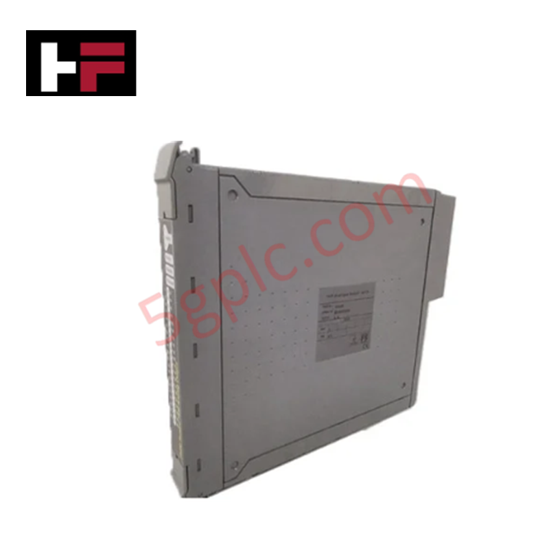
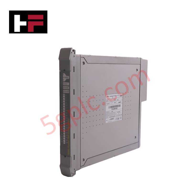
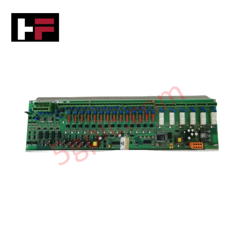
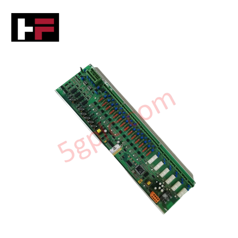
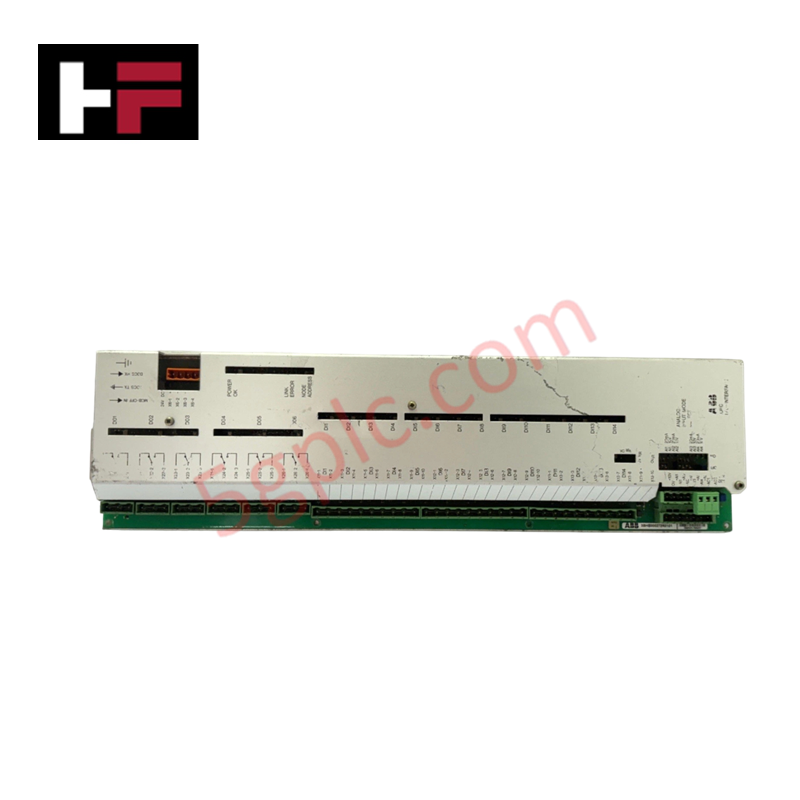
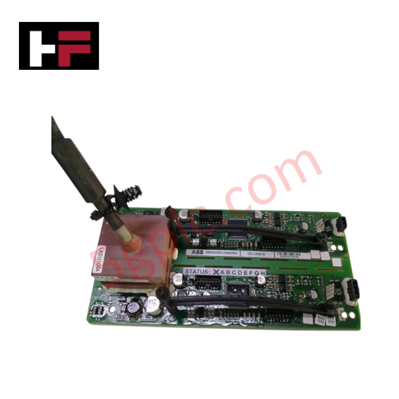
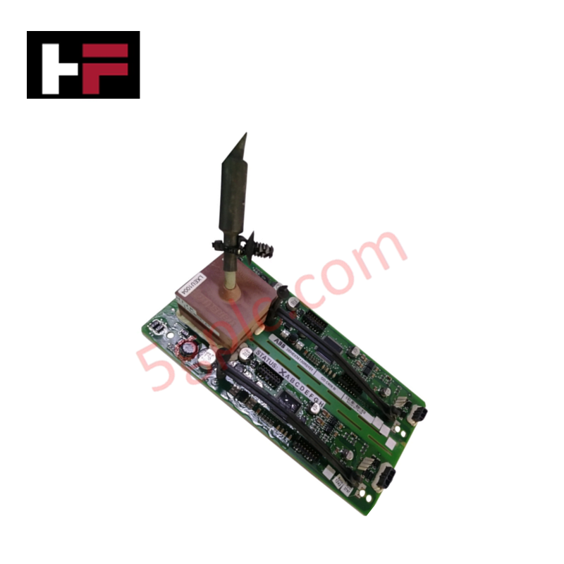
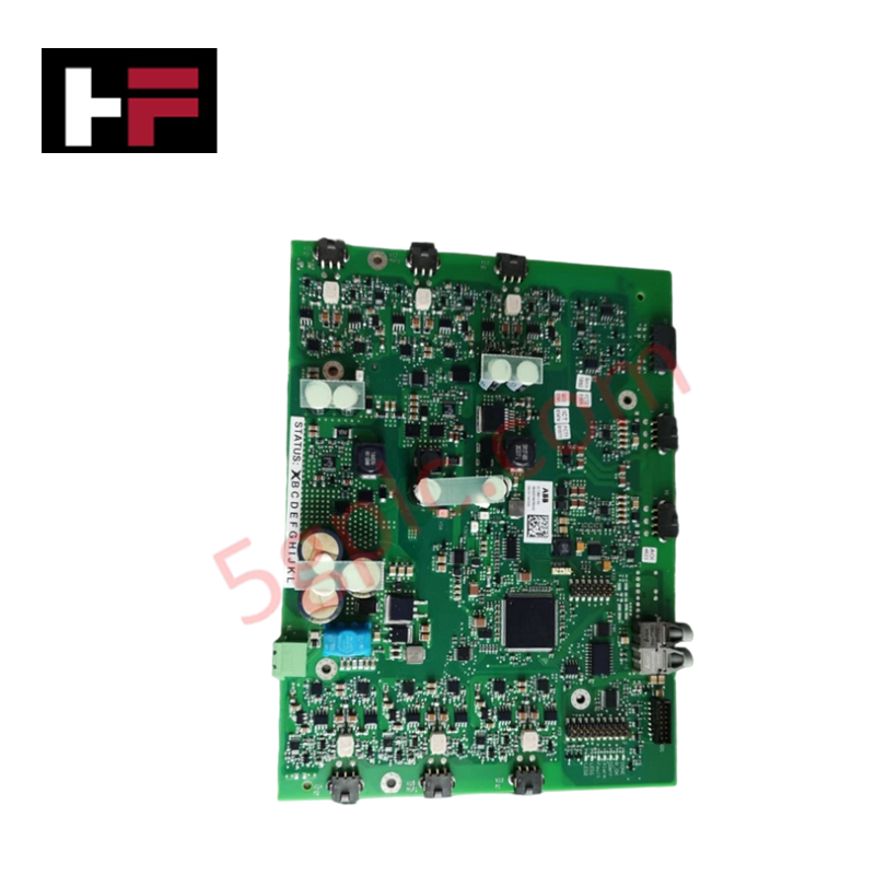
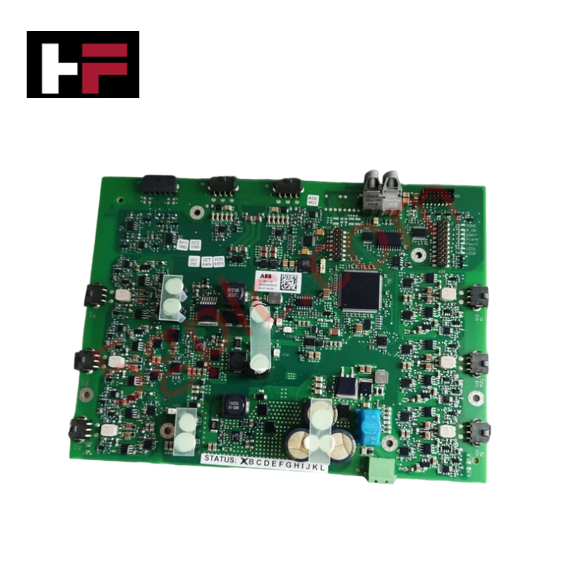
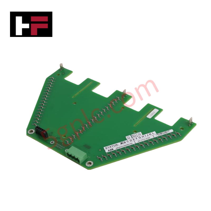
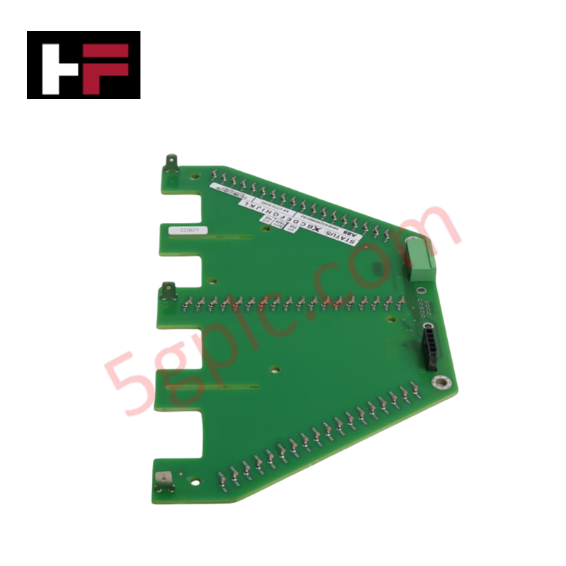
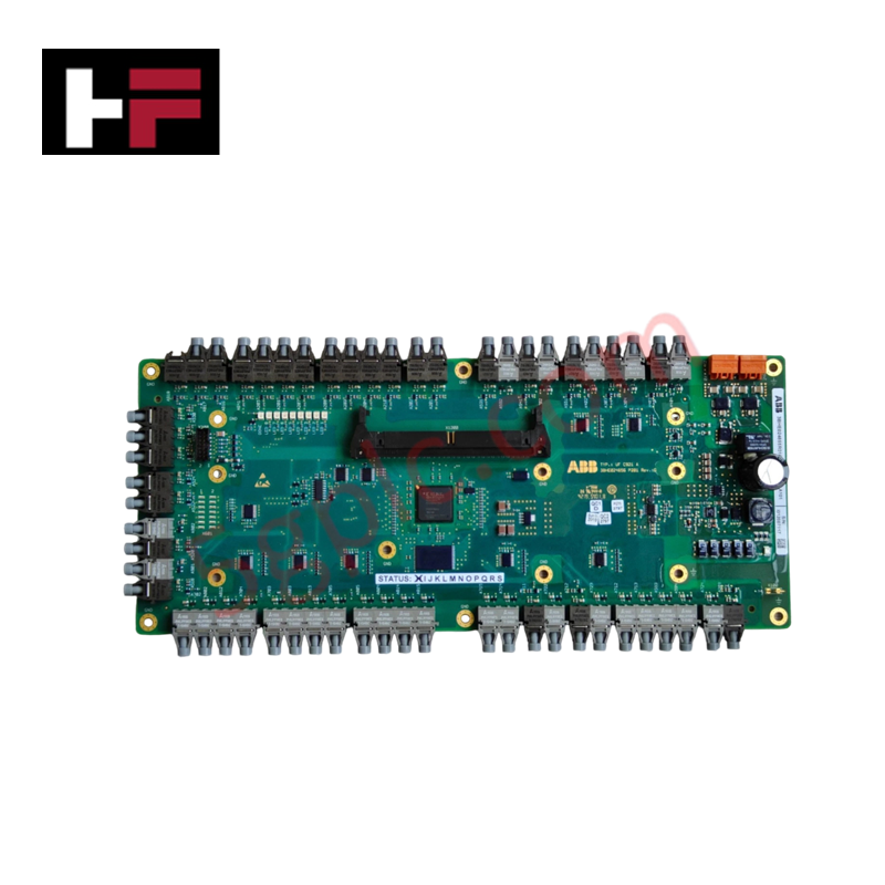
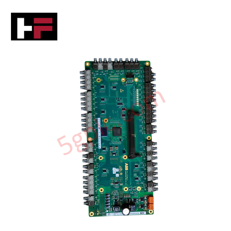
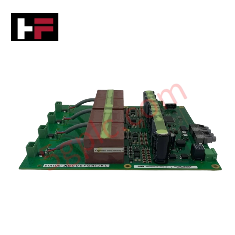
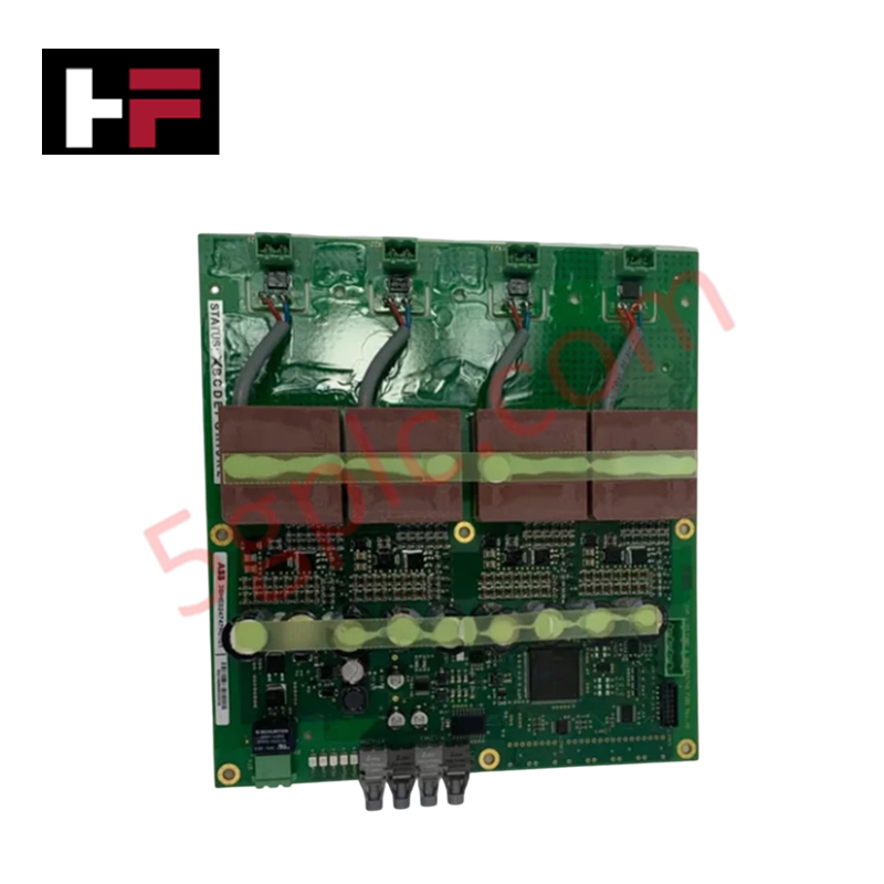
The ABB 3BHB003041R0101, also cataloged as the UF C719 AE101 IOEC I/O Interface, operates as a dedicated hardware component for high-voltage signal conditioning and process loop interface execution within power electronic converter and drive systems. The unit interfaces system control electronics with power stages rated up to 4160 V input and output, processing real-time current and frequency feedback.
Hardware Specifications
| Parameter | Specification |
|---|---|
| Model | 3BHB003041R0101 (UF C719 AE101) |
| Brand | ABB |
| Origin | Switzerland |
| Weight | 1.18 kg |
| Dimensions | 45.3 cm x 12.8 cm x 4.8 cm |
| Operating Temp | 0 to +55 deg C |
| Power Consumption | Standard internal system backplane supply load |
| Product Type | I/O Interface Modules |
| Rated Input Voltage | 4160 V |
| Rated Input Current | 108 A |
| Output Voltage Range | 0 to 4160 V |
| Output Frequency Range | 0 to 75 Hz |
| Max Permissible Short-Circuit Current | 45 kA |
Backplane Bus Communication Velocity & I/O Density Scaling
The UF C719 AE101 I/O interface board maintains high backplane bus communication velocity to enable real-time signal transmission across the power converter rack architecture. The hardware logic scales channel density across multi-phase drive outputs while maintaining firmware flash compatibility with main controller processors. Integrated signal isolation barriers protect low-voltage control circuits from high-voltage transient surges up to rated short-circuit limits.
Frequently Asked Questions
Q: What power stage ratings are supported by the UF C719 AE101 interface module? A: The interface is rated for operation in systems with 4160 V input/output line voltages and output frequencies ranging from 0 to 75 Hz.
Q: Is hot-swapping supported for the 3BHB003041R0101 module? A: No, all high-voltage inputs and internal power supply buses must be completely isolated and de-energized before inserting or removing the assembly to prevent electrical shock or hardware damage.
Q: How is electromagnetic interference mitigated across high-power interfaces? A: The module relies on internal galvanic/optoelectronic isolation components and shielded backplane connectors to prevent high-voltage switching noise from disturbing control logic.
Field Installation Guidelines
- Isolate all high-voltage power feeds (up to 4160 V) and auxiliary control power before accessing the module mounting area.
- Wear a grounded wrist strap to prevent static discharge damage to onboard interface components during physical handling.
- Align the card with the rack chassis slots and push straight in until backplane connections seat fully.
- Tighten front panel mounting screws to secure mechanical locking and establish continuous frame grounding to the chassis.
- Ensure all field control and feedback cables are shielded twisted pairs with shield drain wires attached to the main grounding bar.
Additional Information
- 100% Genuine Parts: All products are original and authentic, ensuring reliable industrial performance.
- 30-Day Refund Guarantee: Return any in-stock item within 30 days in original, unopened packaging for a full refund (excluding shipping and fees).
- 12-Month Warranty: Covers defects in materials or workmanship; excludes misuse, normal wear, or unauthorized modifications.
- Worldwide Shipping: We ship via USPS, UPS, FedEx, and DHL. Delivery times vary by country and may be subject to customs or import fees.
- Support & Contact: Technical and warranty assistance is available anytime. Contact us here: Contact.
- Purchase Guidance: Check product specifications and compatibility carefully before ordering to ensure proper application.
Tech & Buying Guide

Why 24V DC Is the Universal Standard for Industrial Automation Power Supplies
Industrial manufacturing requires continuous uptime to prevent equipment damage. Unlike AC power, 24V DC circuits seamlessly integrate with UPS units and battery banks. During main grid failures, a 24V DC backup system instantly maintains PLC memory, instrument loops, and critical safety valves without interruption.

Site Acceptance Testing (SAT) for PLC Control Systems: An Engineering Execution Guide
The Site Acceptance Test (SAT) represents the definitive handover stage in industrial automation projects. While the Factory Acceptance Test confirms cabinet hardware assembly off-site, the SAT validates real-world performance under live site conditions. Consequently, a structured execution strategy prevents equipment damage and guarantees seamless integration into plant operations.

Mastering the Factory Acceptance Test (FAT) for PLC Control Panels: An Expert Guide
The Factory Acceptance Test (FAT) is a vital milestone in industrial automation that ensures custom PLC panels meet exact design specifications before dispatch. This guide outlines the step-by-step FAT procedure and key industry best practices to prevent costly site delays and ensure long-term operational success.