










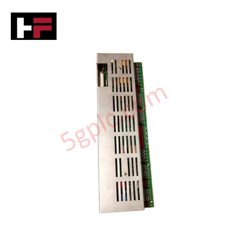
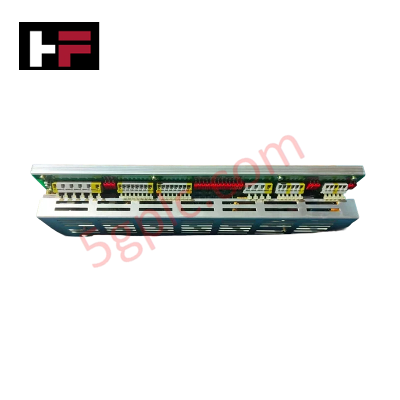
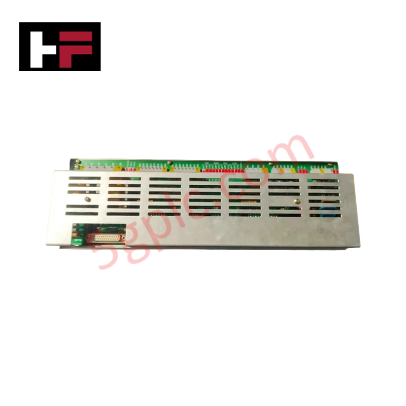
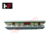
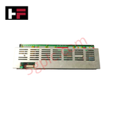
Product Details
The ABB UA C317 AE HIEE300725R0001, also cataloged as the UA C317 AE Interface Card, operates as a dedicated hardware component for analog signal conditioning and variable frequency drive (VFD) output modulation within ABB control platforms. The card converts internal control registers into galvanically isolated 0-10 VDC or 0-20 mA analog outputs to command field actuators and speed reference loops. With a signal response latency under 10 ms and +/-0.1% full scale accuracy, it ensures real-time feedback processing across low-voltage logic interfaces and high-power motor control units.
Hardware Specifications
| Parameter | Specification |
|---|---|
| Model | UA C317 AE HIEE300725R0001 |
| Brand | ABB |
| Origin | Switzerland |
| Weight | 4.54 kg (10.00 lbs) net |
| Dimensions | 100.0 mm x 220.0 mm x 150.0 mm (3.94 in x 8.66 in x 5.91 in) |
| Operating Temp | -40 to +70 deg C (Storage: -40 to +85 deg C) |
| Power Consumption | ~5 W (at 24 VDC nominal supply) |
| Output Options | 0-10 VDC or 0-20 mA analog output |
| Response Time | < 10 ms |
| Accuracy | +/-0.1% full scale |
| Isolation Voltage | 500 VAC (typical) |
Backplane Bus Communication Velocity and Firmware Flash Compatibility
The UA C317 AE module links directly into the system backplane to achieve deterministic signal updating with minimal latency. High backplane bus communication velocity ensures rapid clock synchronization between central processing units and the card's digital-to-analog conversion stages. Non-volatile onboard memory ensures firmware flash compatibility, allowing persistent configuration storage and system software updates across power interruption cycles.
Frequently Asked Questions
Q: Can the UA C317 AE card be removed or inserted while the system rack is powered?
A: No. System power to the rack backplane and the 24 VDC external supply must be de-energized prior to installing or removing the card to prevent arc erosion on edge contacts and internal logic disruption.
Q: How is galvanic isolation maintained between the field output channels and system logic?
A: The board incorporates internal isolation barriers rated at 500 VAC, preventing high-voltage ground loops and field noise from entering the backplane control bus.
Q: What power source is required to drive the onboard analog conversion circuitry?
A: The module requires an external input voltage of 24 VDC, drawing approximately 5 W under full load operation.
Field Installation Guidelines
- Disconnect the main 24 VDC supply and verify that all field actuator wiring loops are de-energized prior to card placement.
- Align the module circuit board edges with the chassis slot guides and slide the card inward until the backplane contacts engage fully.
- Tighten the retaining hardware on the front plate to ensure mechanical stability and establish low-impedance ground connection to the chassis.
- Route 0-10 VDC and 0-20 mA signal wiring separately from AC power cables to prevent inductive noise coupling.
- Utilize shielded twisted-pair cables for analog output connections, terminating cable shields at the panel earth bar near the cabinet entry gland.
Additional Information
- 100% Genuine Parts: All products are original and authentic, ensuring reliable industrial performance.
- 30-Day Refund Guarantee: Return any in-stock item within 30 days in original, unopened packaging for a full refund (excluding shipping and fees).
- 12-Month Warranty: Covers defects in materials or workmanship; excludes misuse, normal wear, or unauthorized modifications.
- Worldwide Shipping: We ship via USPS, UPS, FedEx, and DHL. Delivery times vary by country and may be subject to customs or import fees.
- Support & Contact: Technical and warranty assistance is available anytime. Contact us here: Contact.
- Purchase Guidance: Check product specifications and compatibility carefully before ordering to ensure proper application.









Tech & Buying Guide
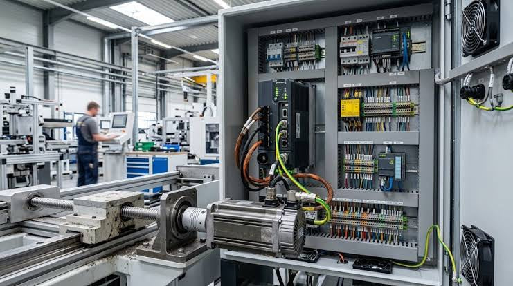
Demystifying Programmable Logic Controllers: Comprehensive Guide to PLC Classification and Selection in Industrial Automation
Modern industrial automation heavily relies on Programmable Logic Controllers (PLCs) to drive factory floor efficiency. Over my 15 years as an industrial automation expert working with DCS, TSI, and control systems, I have seen PLCs evolve into the central nervous system of modern manufacturing. Selecting the right controller requires a deep understanding of PLC types based on physical size, hardware architecture, and power supply configurations.

Comprehensive Guide to PLC Types in Modern Industrial Automation
Modern industrial automation relies on programmable logic controllers to govern critical factory operations. System integrators classify PLCs based on scale, hardware architecture, and power supply design. Understanding these core categories enables automation engineers to select the right control system architecture. Consequently, proper hardware selection optimizes performance while minimizing long-term operational costs.

Demystifying the DDE Protocol in Legacy Industrial Automation Systems
Modern control systems rely heavily on seamless interprocess communication to exchange operational data between software programs. Microsoft first introduced the Dynamic Data Exchange (DDE) protocol in 1987 to enable real-time data sharing. In factory automation, DDE served as an early bridge between control software and Windows desktop applications. Therefore, understanding DDE mechanics provides crucial insights into how legacy industrial networks established software-level connectivity.