










Product Details
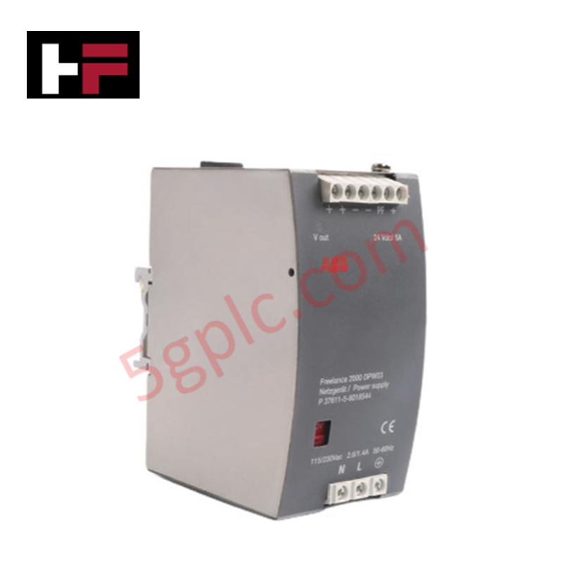
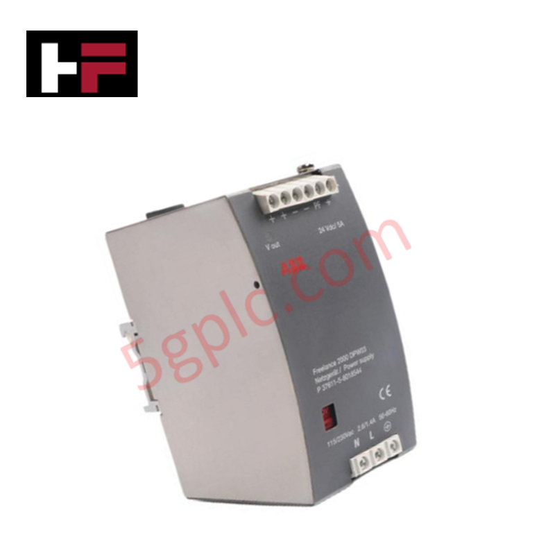
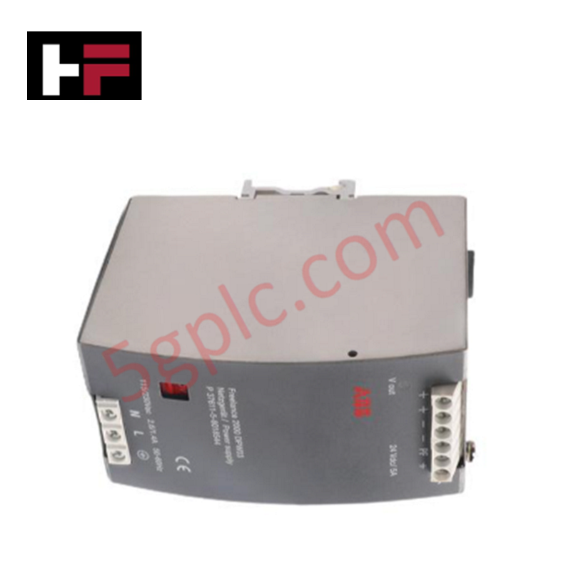
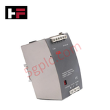
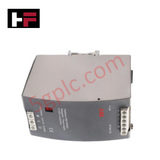
The ABB DPW03, also cataloged as the DPW03 Auxiliary Power Supply, operates as a dedicated hardware component for power conversion and voltage stabilization tasks within industrial automation and control networks.
Hardware Specifications
| Parameter | Specification |
|---|---|
| Model | DPW03 |
| Brand | ABB |
| Origin | Sweden / Europe standard sourcing |
| Weight | 2 kg |
| Dimensions | Compact footprint design allocation |
| Operating Temp | 0 to 60 deg C |
| Power Consumption | 115 / 230 VAC Input Execution |
| Product Type | Auxiliary Power Supplies |
| Output Voltage | 24 VDC |
| Output Current | 5 A |
| Protection Circuits | Integrated overcurrent and overvoltage protection |
Deterministic Network Routing and I/O Density Scaling
The ABB DPW03 delivers a stable 24 VDC output loop rated up to 5 A to support dense physical nodes and facilitate localized I/O density scaling routines. By maintaining a fixed direct-current field distribution block separate from the internal rack framework, this module prevents local voltage drops from compromising backplane bus communication velocity across nearby automation cards. The hardwired regulation circuitry filters incoming line disturbances, sustaining deterministic tracking dynamics and verifying long-term firmware flash compatibility for all interconnected control elements across the shared sub-rack.
Frequently Asked Questions
Q: What are the primary electrical isolation limitations during an overcurrent or overvoltage event?
A: The onboard overcurrent and overvoltage shutdown systems isolate the 24 VDC field distribution side from the 115/230 VAC input grid. This protective decoupling prevents hardware damage, though it forces connected field modules into an unpowered fault state until reset.
Q: Is this auxiliary power supply unit rated for hot-swapping under live input voltage?
A: No. Input line connections carrying 115 VAC or 230 VAC must be completely de-energized at the external terminal breaker before physically mounting, unmounting, or servicing any input terminal wiring blocks.
Field Installation Guidelines
- Mount the assembly securely inside an industrial enclosure, allowing adequate vertical clear zone distances for proper thermal dissipation.
- Select the correct primary input line configuration matching the local grid infrastructure before terminating live 115 VAC or 230 VAC connections.
- Establish a low-impedance connection between the primary ground terminal screw and the plant instrumentation earth network.
- Route the 24 VDC output cables along dedicated low-voltage wire ways, keeping proper physical isolation boundaries away from separate high-current AC lines.
Additional Information
- 100% Genuine Parts: All products are original and authentic, ensuring reliable industrial performance.
- 30-Day Refund Guarantee: Return any in-stock item within 30 days in original, unopened packaging for a full refund (excluding shipping and fees).
- 12-Month Warranty: Covers defects in materials or workmanship; excludes misuse, normal wear, or unauthorized modifications.
- Worldwide Shipping: We ship via USPS, UPS, FedEx, and DHL. Delivery times vary by country and may be subject to customs or import fees.
- Support & Contact: Technical and warranty assistance is available anytime. Contact us here: Contact.
- Purchase Guidance: Check product specifications and compatibility carefully before ordering to ensure proper application.









Tech & Buying Guide

Will PLCs Become Obsolete? The Future of Control Systems in Industry 4.0
Modern manufacturing is undergoing a rapid technological transformation driven by Industry 4.0 innovations. Technologies like Artificial Intelligence (AI), Machine Learning (ML), and the Industrial Internet of Things (IIoT) are dominating discussions across the factory automation sector. Consequently, many engineers wonder if these advanced digital tools will eventually replace traditional Programmable Logic Controllers (PLCs). However, evaluating the core physics of industrial operations reveals a very different reality for control systems.

Demystifying Open Platform Communication (OPC): The Backbone of Industrial Interoperability
Interoperability remains a cornerstone requirement for modern smart factories and process automation. Open Platform Communication (OPC) bridges the gap between disparate hardware platforms, control systems, and visualization software. By establishing a universal communication standard, OPC allows field controllers, SCADA platforms, and enterprise software from different vendors to exchange real-time data seamlessly.

Understanding Siemens PLC Memory Cards: MMC, SMC, and SD Solutions in Industrial Automation
Memory management plays a pivotal role in maintaining control system reliability across modern manufacturing plants. Industrial control systems rely on specialized memory cards to store project logic, firmware updates, and retentive system data. Siemens uses several memory architectures, including Micro Memory Cards (MMC) and SIMATIC Memory Cards (SMC). Engineers must understand these hardware variations to ensure zero data loss and minimize downtime during maintenance routines.