


Product Details
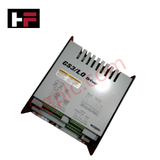
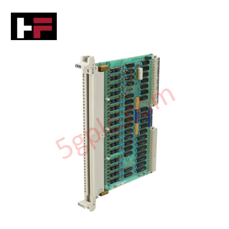
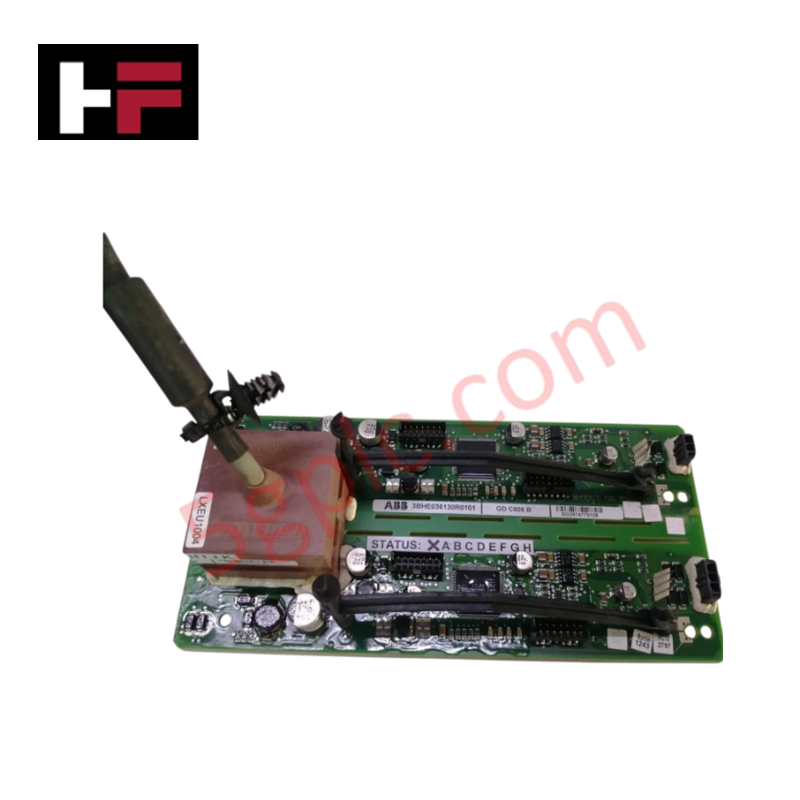
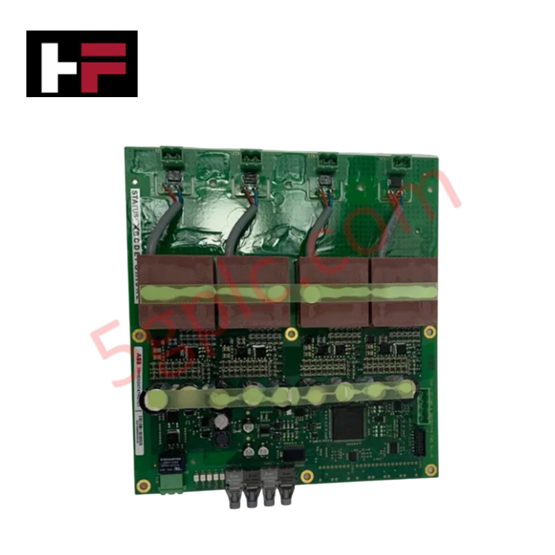
Configured for actuator interface in GS3/LQ control systems, the Woodward 9907-135 (9907-135 Driver Module) provides direct electrical execution of 4-20 mA demand signal conversion to output drive signals.
Hardware Specifications
| Parameter | Specification |
|---|---|
| Model | 9907-135 |
| Brand | Woodward |
| Origin | USA |
| Weight | 0.38 kg |
| Dimensions | 15.8 cm x 15.8 cm x 4.0 cm |
| Input Voltage | 10-32 VDC |
| Input Signal | 4-20 mA Demand |
Actuator Loop Feedback Response and Thermal Heat Sink Dissipation Profiles
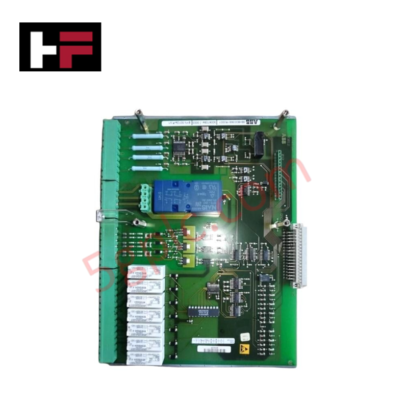
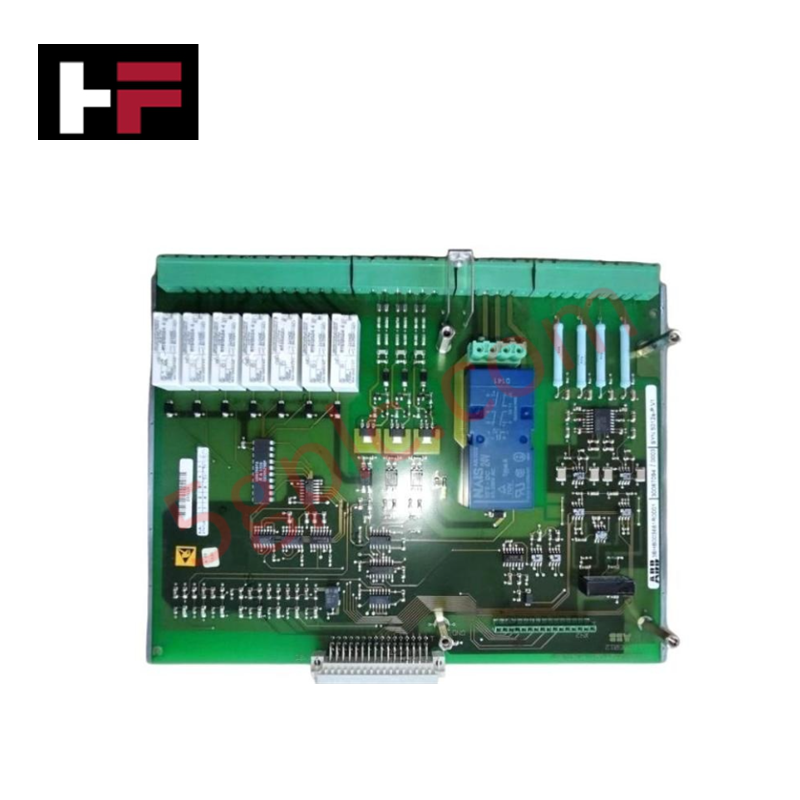
The 9907-135 driver module processes 4-20 mA demand signals to regulate output current for GS3/LQ series actuators. The module facilitates a stable actuator loop feedback response by maintaining precise current output proportional to the input command. Thermal heat sink dissipation profiles are managed by the module housing to support the internal power stage during operation across the specified 10-32 VDC input range. The circuit ensures minimal latency between command input and driver output, maintaining control accuracy for proportional valve or actuator positioning.
Frequently Asked Questions
Q: Can the 9907-135 be used with input voltages outside the 10-32 VDC range?
A: No. Operating the module outside the specified voltage range may result in internal component failure or erratic output behavior. Ensure the power source is regulated within the 10-32 VDC limits.
Q: Is the 4-20 mA input signal isolated from the module power ground?
A: The input is designed to receive standard 4-20 mA control signals. Standard practice requires ensuring the signal source and the driver module power supply share a common reference point if isolation is not explicitly defined in the site-specific control schematic.
Field Installation Guidelines
- Mounting: Secure the module using the provided mounting holes. Maintain adequate clearance around the 15.8 cm x 15.8 cm x 4.0 cm footprint to facilitate convective cooling.
- Wiring: Terminate field connections using the screw clamp terminals. Ensure wire gauges are appropriate for the 10-32 VDC power draw and 4-20 mA signal transmission.
- Shielding: Use shielded twisted-pair cables for the 4-20 mA demand signal input. Terminate shields at the control cabinet ground to prevent electromagnetic interference from skewing the command signal.
- Inspection: Verify terminal tightness after initial installation to prevent intermittent connections that could cause signal loss or erratic actuator positioning.
Additional Information
- 100% Genuine Parts: All products are original and authentic, ensuring reliable industrial performance.
- 30-Day Refund Guarantee: Return any in-stock item within 30 days in original, unopened packaging for a full refund (excluding shipping and fees).
- 12-Month Warranty: Covers defects in materials or workmanship; excludes misuse, normal wear, or unauthorized modifications.
- Worldwide Shipping: We ship via USPS, UPS, FedEx, and DHL. Delivery times vary by country and may be subject to customs or import fees.
- Support & Contact: Technical and warranty assistance is available anytime. Contact us here: Contact.
- Purchase Guidance: Check product specifications and compatibility carefully before ordering to ensure proper application.

Tech & Buying Guide
Mastering Functional Safety Terminology in Industrial Automation
In modern process control and factory automation, managing operational risk is a top engineering priority. High-speed machinery, high-pressure vessels, and continuous processes present constant hazards to personnel and equipment. Modern plant operations rely heavily on functional safety strategies to mitigate these risks. This guide breaks down the essential functional safety terminology that every control systems engineer should master.

Understanding Dry Contacts in PLC Wiring: An Industrial Automation Guide
Mastering contact switching principles is essential for reliable control panels. Field devices and PLCs interface through dry or wet contacts. This technical guide examines the mechanics of dry contacts, explores their wiring architectures, and evaluates their key advantages in industrial automation.

Ultimate Commissioning Checklist for Industrial Automation Systems: An Engineering Guide
Commissioning is the most decisive phase of an industrial automation project, transforming control hardware and software into an operational facility. Thorough testing prevents costly startup delays and builds customer confidence. This guide covers essential checklists, electrical standards, and best practices.