










Product Details
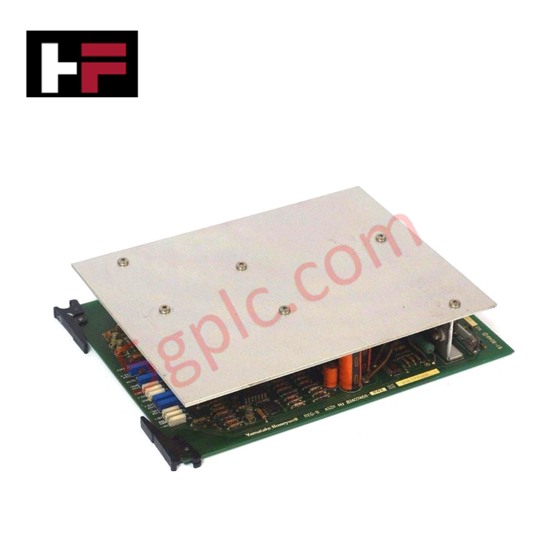
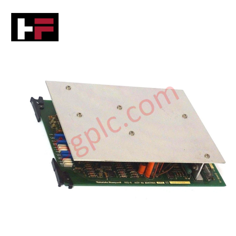
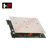
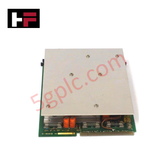
The Honeywell 82407468-002, also cataloged as the 82407468 MC Regulator Board, operates as a dedicated hardware component for secondary voltage regulation within Multifunction Controller Point Card File PF-200 networks. The board conditions an incoming primary DC power rail and converts it into isolated lower-voltage distributions required to drive backend internal logic and analog circuitry over the chassis backplane.
Hardware Specifications
| Parameter | Specification |
|---|---|
| Model | 82407468-002 |
| Brand | Honeywell |
| Origin | USA |
| Weight | Standard Chassis Card Weight |
| Dimensions | Standard PF-200 Card File Slot Footprint |
| Operating Temp | 0 to 60 deg C |
| Power Consumption | Backplane Load Dependent |
| Input Rating | 24 VDC |
| Output Voltages | +5 VDC, +15 VDC, -15 VDC |
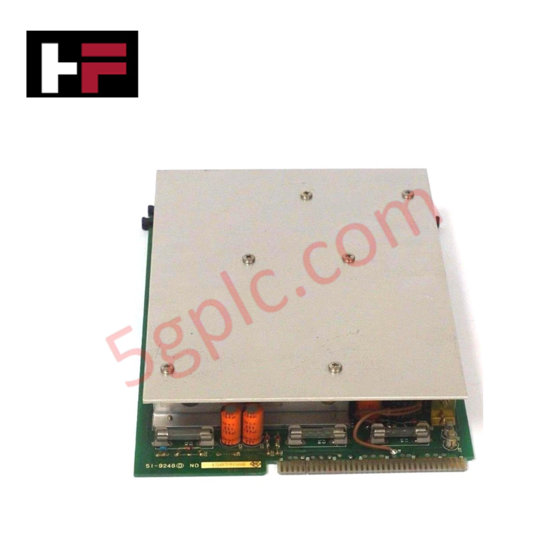
| Protection Layout | F1 (5 A), F2 (2 A), F3 (5 A) |
| Indicator System | LD1 (+24 VDC Present), LD2 (All Voltages Present) |
| Test Point Access | TP1 (+24 VDC), TP2 (+12 VDC), TP3 (Common), TP4 (+15 VDC), TP5 (Analog Common), TP6 (-15 VDC) |
Honeywell Channel-to-Channel Isolation & Analog Distribution
To support processing stability across the card file during active analog input sampling, this hardware platform enforces direct channel-to-channel isolation criteria between the digital logic components and the analog measurement subsystems. Separate ground paths, accessible via dedicated test points for digital and analog common connections, suppress cross-talk and prevent line noise propagation across the backplane bus, maintaining total loop integrity across the entire instrumentation rack.
Frequently Asked Questions
Q: What are the distinct voltage thresholds output to the backplane assembly by this board?
A: The board receives a nominal 24 VDC supply line and regulates it down to generate independent +5 VDC, +15 VDC, and -15 VDC rails directly for backplane consumption.
Q: How can field technicians verify local voltage health on the card frame?
A: Technical staff can observe the integrated diagnostic LEDs: LD1 illuminates when +24 VDC is detected on the backplane, and LD2 indicates that all secondary regulated voltages are successfully present.
Q: What overcurrent protection elements are physically populated on this module?
A: The card contains three dedicated physical fuses labeled as F1 (rated at 5 A), F2 (rated at 2 A), and F3 (rated at 5 A) to safeguard separate internal voltage branches against short-circuit hazards.
Field Installation Guidelines
- Isolate and de-energize the primary 24 VDC power feed supplying the Multifunction Controller Point Card File PF-200 chassis before executing installation routines.
- Direct the card into its designated slot guides, pushing smoothly until the rear pin header makes firm electrical contact with the backplane connectors.
- Utilize a calibrated multimeter across the on-board physical test points (TP1 through TP6) to validate nominal electrical distribution levels against common grounds during commissioning.
- Ensure the analog shield paths are securely landed at the single-point cabinet ground terminal to mitigate low-frequency electromagnetic interference within the analog measurement circuit.
Additional Information
- 100% Genuine Parts: All products are original and authentic, ensuring reliable industrial performance.
- 30-Day Refund Guarantee: Return any in-stock item within 30 days in original, unopened packaging for a full refund (excluding shipping and fees).
- 12-Month Warranty: Covers defects in materials or workmanship; excludes misuse, normal wear, or unauthorized modifications.
- Worldwide Shipping: We ship via USPS, UPS, FedEx, and DHL. Delivery times vary by country and may be subject to customs or import fees.
- Support & Contact: Technical and warranty assistance is available anytime. Contact us here: Contact.
- Purchase Guidance: Check product specifications and compatibility carefully before ordering to ensure proper application.




Tech & Buying Guide

Demystifying CPU Communication Ports in Siemens PLC Architectures
Industrial automation relies heavily on robust data exchange between devices. Without seamless connectivity, field instruments, network switches, human-machine interfaces, and programmable logic controllers cannot coordinate effectively. Therefore, understanding the various CPU communication ports available in Siemens hardware ensures efficient factory automation design and seamless system integration.

Mastering the Siemens PLC Scan Cycle: How the CPU Executes Automation Programs
Industrial automation relies heavily on programmable logic controllers (PLCs) to manage complex manufacturing processes. Many engineers dive straight into programming without mastering the underlying architecture. However, understanding how a PLC CPU executes a program ensures reliable system design. Therefore, mastering the scan cycle optimizes both performance and troubleshooting in modern control systems.

How to Connect to Siemens S7 PLCs: 5 Essential Communication Methods
Establishing a reliable hardware link between a programming terminal and a Siemens SIMATIC controller is essential for engineering workflows. Field engineers rely on distinct physical layers, ranging from legacy serial connections to high-speed Industrial Ethernet protocols. Modern factory automation environments prioritize fast data transfer and seamless driver integration. Selecting the correct connection method simplifies program downloads, online monitoring, and system troubleshooting in complex control systems.