


Product Details
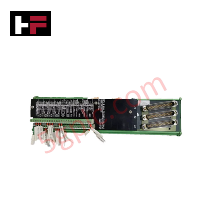
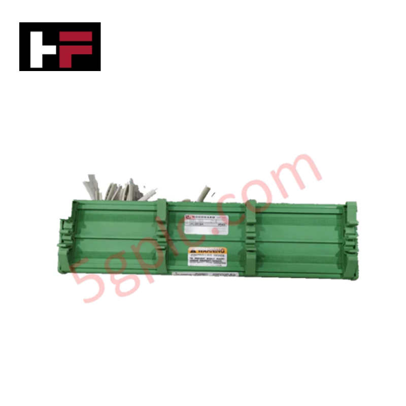
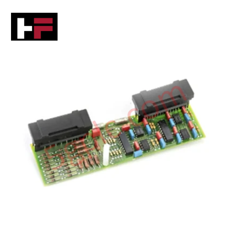
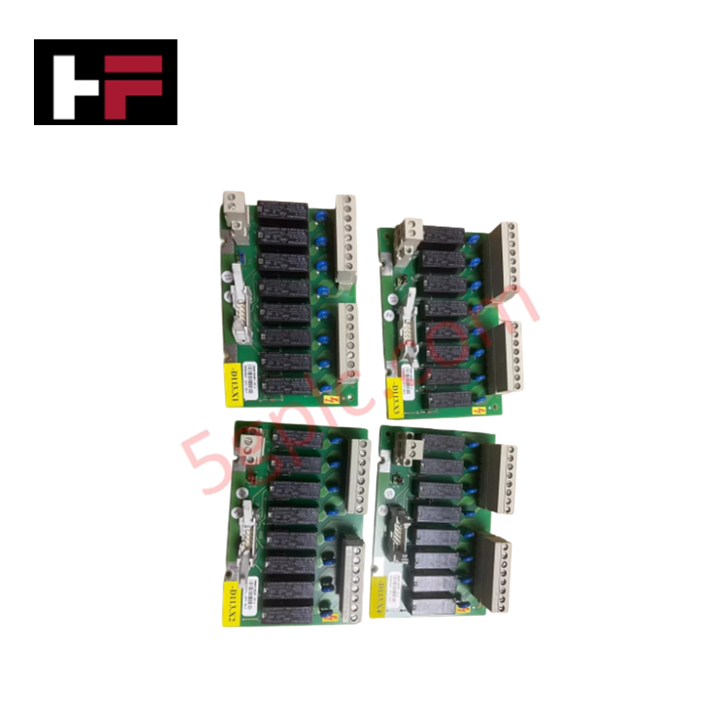
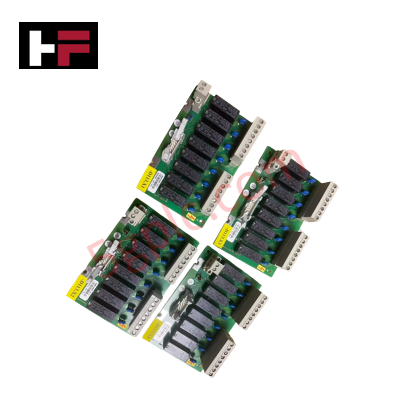
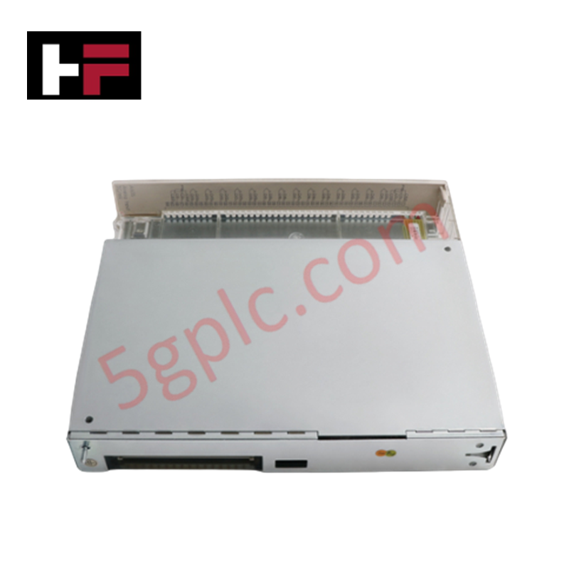
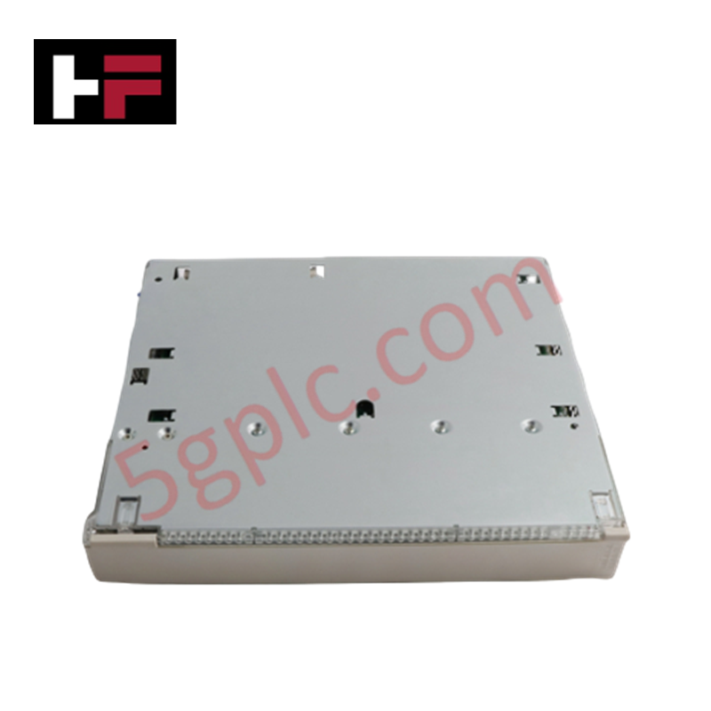
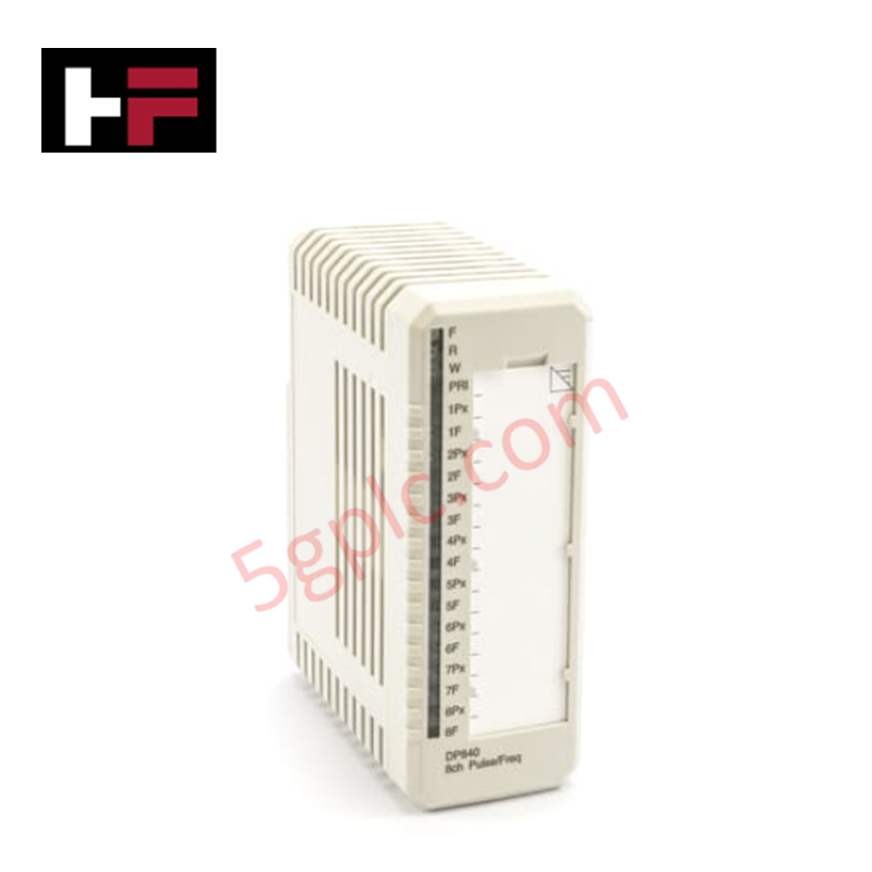
Configured for hydraulic signal regulation in governor control platforms, the Woodward 5501-365 (5501-365 Electro-hydraulic Converter) provides direct physical/electrical execution of electrical-to-hydraulic signal conversion.
Hardware Specifications
| Parameter | Specification |
|---|---|
| Model | 5501-365 |
| Brand | Woodward |
| Dimensions | 100 x 50 x 30 mm |
| Operating Temp | -10 to 60 deg C |
| Power Consumption | Not specified |
| Input Voltage | 24 VDC |
| Output Voltage | 0-10 VDC |
| Output Current | 5 A |
| Communication | RS485 |
Actuator Loop Feedback Response
The 5501-365 functions as an interface between electronic control signals and hydraulic actuation. To maintain a stable actuator loop feedback response, the converter utilizes high-precision internal circuitry to minimize deadband and hysteresis in the hydraulic output. The device accepts 24 VDC input power and processes electronic control commands into 0-10 VDC signals to modulate hydraulic servo valve positioning. The RS485 interface allows for remote monitoring of device status and calibration parameters, ensuring that the actuator response remains synchronized with the prime mover governing requirements under transient load conditions.
Frequently Asked Questions
Q: Does the module support real-time adjustments via the RS485 interface?
A: Yes, the RS485 communication interface allows for the monitoring and adjustment of internal calibration parameters. Ensure the master controller protocol matches the module's baud rate and address settings to maintain data communication integrity.
Q: What are the installation requirements to ensure thermal stability?
A: The device is rated for operation between -10 deg C and 60 deg C. Ensure the module is mounted in a location with adequate airflow, away from direct thermal radiation sources, to maintain the internal heat sink dissipation profiles within design limits.
Field Installation Guidelines
- Mounting: Secure the converter to a rigid, vibration-dampened surface using the designated mounting points on the 100 x 50 x 30 mm chassis.
- Electrical Wiring: Use shielded twisted-pair cabling for the RS485 communication link and high-current rated wire for the power and signal outputs to prevent voltage drops.
- Grounding: Connect the module's common reference to the control cabinet's earth bus to mitigate electromagnetic interference and ensure the accuracy of the 0-10 VDC output signal.
- Validation: Before applying hydraulic pressure, perform an electrical continuity check and verify the 24 VDC supply. Use a diagnostic tool to confirm the module responds correctly to control commands via the RS485 port.
Additional Information
- 100% Genuine Parts: All products are original and authentic, ensuring reliable industrial performance.
- 30-Day Refund Guarantee: Return any in-stock item within 30 days in original, unopened packaging for a full refund (excluding shipping and fees).
- 12-Month Warranty: Covers defects in materials or workmanship; excludes misuse, normal wear, or unauthorized modifications.
- Worldwide Shipping: We ship via USPS, UPS, FedEx, and DHL. Delivery times vary by country and may be subject to customs or import fees.
- Support & Contact: Technical and warranty assistance is available anytime. Contact us here: Contact.
- Purchase Guidance: Check product specifications and compatibility carefully before ordering to ensure proper application.
Tech & Buying Guide
Mastering Functional Safety Terminology in Industrial Automation
In modern process control and factory automation, managing operational risk is a top engineering priority. High-speed machinery, high-pressure vessels, and continuous processes present constant hazards to personnel and equipment. Modern plant operations rely heavily on functional safety strategies to mitigate these risks. This guide breaks down the essential functional safety terminology that every control systems engineer should master.

Understanding Dry Contacts in PLC Wiring: An Industrial Automation Guide
Mastering contact switching principles is essential for reliable control panels. Field devices and PLCs interface through dry or wet contacts. This technical guide examines the mechanics of dry contacts, explores their wiring architectures, and evaluates their key advantages in industrial automation.

Ultimate Commissioning Checklist for Industrial Automation Systems: An Engineering Guide
Commissioning is the most decisive phase of an industrial automation project, transforming control hardware and software into an operational facility. Thorough testing prevents costly startup delays and builds customer confidence. This guide covers essential checklists, electrical standards, and best practices.