


Product Details
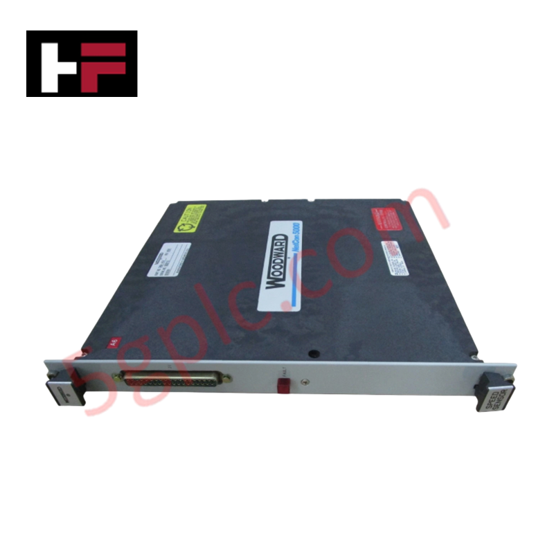
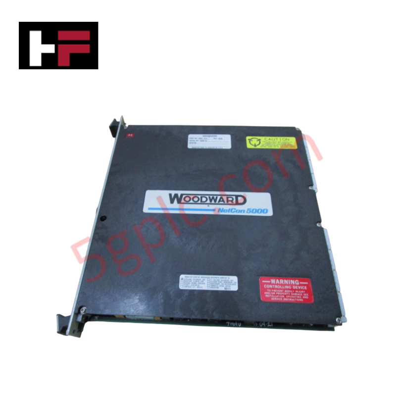
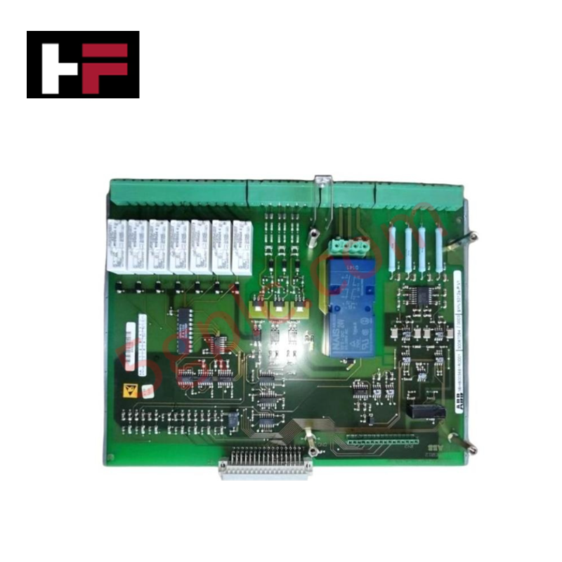
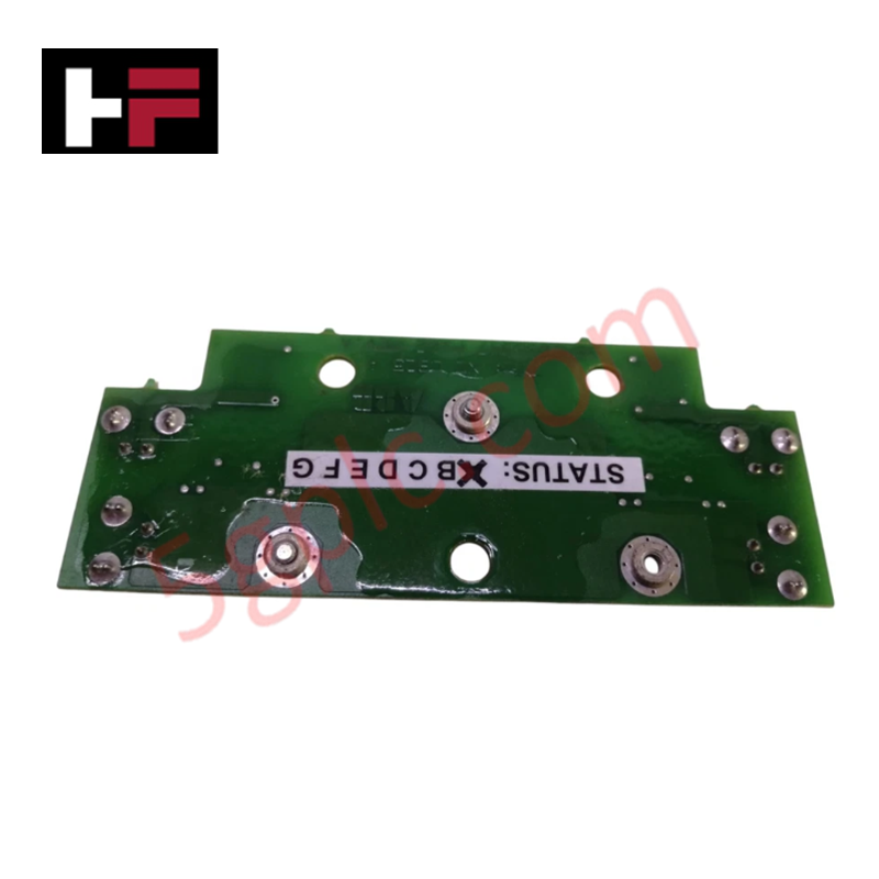
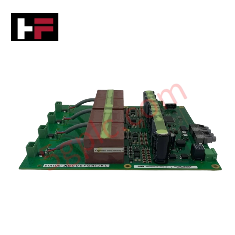
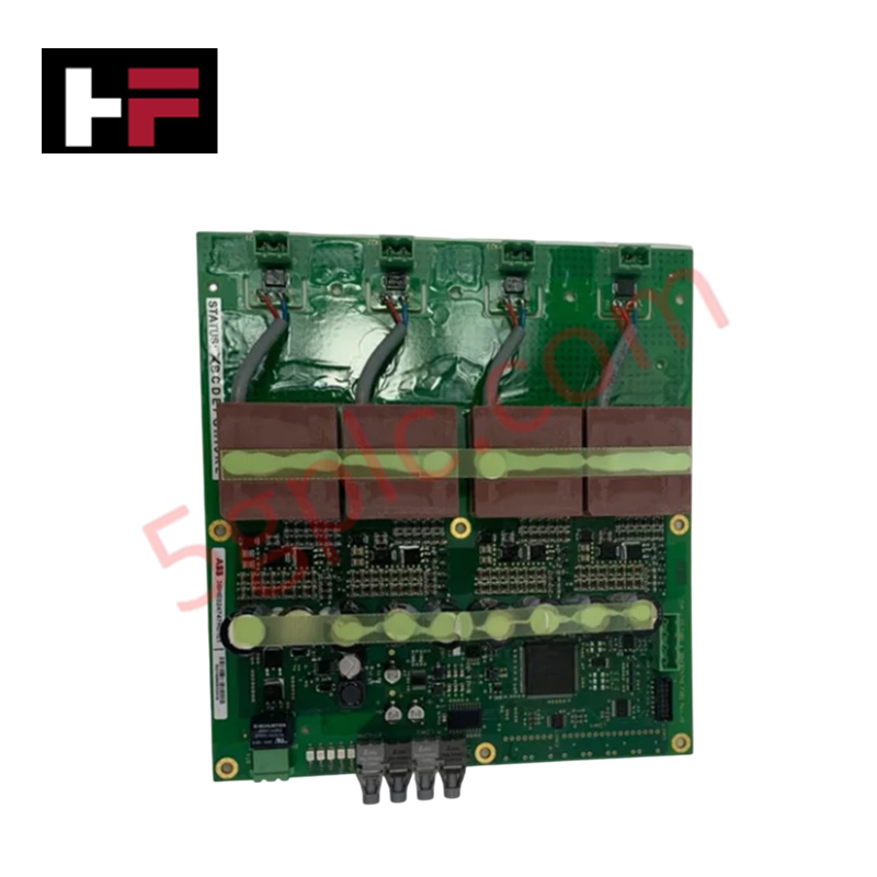
Configured for thermal signal acquisition in NETCON 5000 control platforms, the Woodward 5464-013 (5464-013 RTD Input Driver Module) provides direct physical/electrical execution of semi-insulated RTD signal conditioning.
Hardware Specifications
| Parameter | Specification |
|---|---|
| Model | 5464-013 |
| Brand | Woodward |
| Origin | Not specified |
| Weight | 1.85 lbs |
| Input Type | RTD (Semi-insulated) |
| Fault Indication | Red LED |
| Mounting | Panel Mount |
V/Hz and Field-Oriented Vector Control
The 5464-013 is utilized within the NETCON 5000 architecture to convert resistance-temperature detector (RTD) signals into the process variables required for thermal management and control. In the context of governing applications, precise temperature feedback is required to execute V/Hz and field-oriented vector control algorithms, particularly for cooling fan modulation and thermal protection of the prime mover. The semi-insulated input design helps mitigate ground loops and common-mode interference, ensuring that the control system maintains a stable actuator loop feedback response even when exposed to the electromagnetic environment of large-scale generator systems.
Frequently Asked Questions
Q: What does the red LED indicator signify on the front panel?
A: The red LED functions as a hardware-level fault diagnostic indicator. Illumination indicates an open circuit, short circuit, or out-of-range signal on the connected RTD input channels.
Q: Can this module be installed in a standard rack configuration?
A: The module is designed for panel mounting. Ensure that the panel surface is grounded to provide a reference for the module's shielding and to maintain electrical immunity against radiated noise.
Field Installation Guidelines
- Mounting: Fix the module to a secure, flat panel using the designated mounting holes. Ensure adequate space for thermal dissipation and terminal wiring.
- RTD Wiring: Use high-quality, shielded extension wire for all RTD inputs. Connect the cable shield to a single point at the chassis ground to prevent ground loops that could introduce offset errors in the temperature reading.
- Signal Segregation: Route RTD input wiring away from high-power AC output cabling or motor drive cabling to prevent induced noise on the sensitive resistance-measurement loop.
- Validation: Before final commissioning, measure the resistance of each connected RTD at the terminal block to ensure values fall within the expected operating range and confirm the module detects no faults.
- Fault Monitoring: Verify the status of the red LED during system startup; if illuminated, inspect the physical RTD probe and wire continuity before clearing the fault in the control software.
Additional Information
- 100% Genuine Parts: All products are original and authentic, ensuring reliable industrial performance.
- 30-Day Refund Guarantee: Return any in-stock item within 30 days in original, unopened packaging for a full refund (excluding shipping and fees).
- 12-Month Warranty: Covers defects in materials or workmanship; excludes misuse, normal wear, or unauthorized modifications.
- Worldwide Shipping: We ship via USPS, UPS, FedEx, and DHL. Delivery times vary by country and may be subject to customs or import fees.
- Support & Contact: Technical and warranty assistance is available anytime. Contact us here: Contact.
- Purchase Guidance: Check product specifications and compatibility carefully before ordering to ensure proper application.

Tech & Buying Guide
Mastering Functional Safety Terminology in Industrial Automation
In modern process control and factory automation, managing operational risk is a top engineering priority. High-speed machinery, high-pressure vessels, and continuous processes present constant hazards to personnel and equipment. Modern plant operations rely heavily on functional safety strategies to mitigate these risks. This guide breaks down the essential functional safety terminology that every control systems engineer should master.

Understanding Dry Contacts in PLC Wiring: An Industrial Automation Guide
Mastering contact switching principles is essential for reliable control panels. Field devices and PLCs interface through dry or wet contacts. This technical guide examines the mechanics of dry contacts, explores their wiring architectures, and evaluates their key advantages in industrial automation.

Ultimate Commissioning Checklist for Industrial Automation Systems: An Engineering Guide
Commissioning is the most decisive phase of an industrial automation project, transforming control hardware and software into an operational facility. Thorough testing prevents costly startup delays and builds customer confidence. This guide covers essential checklists, electrical standards, and best practices.