










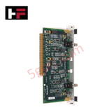
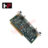
Product Details
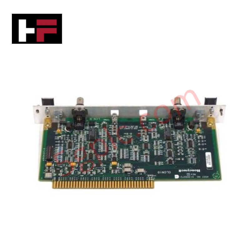
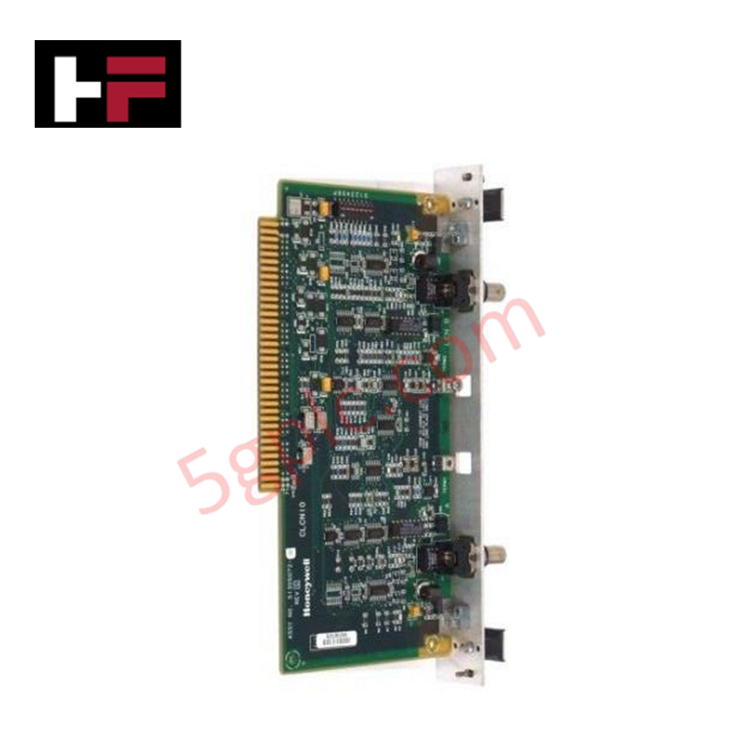
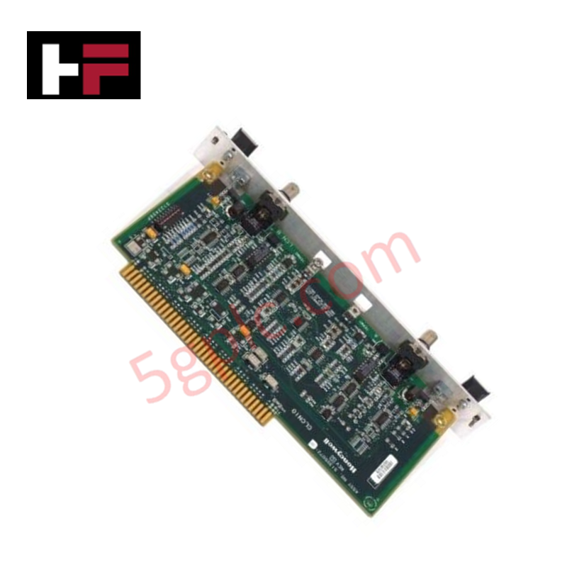
Configured for high-accuracy liquid and gas differential pressure measurement in DCS loops, the Honeywell 51305829-400 (51305829-400 Differential Pressure Transmitter) provides direct physical signal execution through primary process connections.
Hardware Specifications
| Parameter | Specification |
|---|---|
| Model | 51305829-400 |
| Brand | Honeywell |
| Origin | USA / Global Manufacturing |
| Operating Temp | -40 to 82 deg C (-40 to 180 deg F) |
| Power Consumption | Loop-powered via 12-24 VDC supply voltage |
| Measurement Range | 0 to 100 inH2O (0 to 100 inches of water) |
| Overpressure Limit | -1 to 20.7 bar (-15 to 300 psi) |
| Output Protocol | 4-20 mA DC current loop, HART, FOUNDATION Fieldbus |
| Reference Accuracy | +/-0.15% of span (+/-0.25% FS max) |
| Repeatability | +/-0.10% of FS |
| Long-Term Stability | +/-0.05% of span per year |
| Turndown Ratio | 10:1 |
| Enclosure Protection | NEMA 4X / IP66 rated |
| Process Connection | 1/4 in NPT female |
4-20 mA HART Loop Protocol and FOUNDATION Fieldbus Connectivity
The 51305829-400 differential pressure assembly converts piezoresistive element deflection into a calibrated 4-20 mA DC current signal over two-wire loop networks. Integrated digital processing units support HART protocol overlay and option-card FOUNDATION Fieldbus communications, allowing direct integration into centralized DCS asset management software.
Internal signal conditioning includes active temperature compensation operating from -40 to 40 deg C (-40 to 104 deg F) to minimize thermal span errors. Built-in channel-to-channel isolation and surge suppression circuits isolate internal piezoresistive sensing circuitry from field wiring transients and common-mode loop ground potential differences.
Frequently Asked Questions
Q: What power supply range is required to drive the 51305829-400 output loop?
A: The transmitter operates on a 12 to 24 VDC power supply connected directly across the two-wire 4-20 mA current loop terminals.
Q: What process connection size is provided on the transmitter body?
A: Physical process interface ports are standard 1/4 in NPT female connections.
Q: How is thermal baseline drift minimized across changing ambient conditions?
A: Onboard temperature compensation algorithms continuously correct sensor cell output across the -40 to 40 deg C (-40 to 104 deg F) compensated operating band.
Field Installation Guidelines
- Mount the transmitter securely using the integrated bracket holes, ensuring process ports are oriented to allow adequate condensate drainage or impulse line venting.
- Thread impulse piping into the 1/4 in NPT process connections using approved PTFE tape or thread sealant, achieving a minimum of 5 full threads engagement.
- Connect two-wire 4-20 mA loop wiring to the internal terminal block, taking care to properly ground cable shielding at the control cabinet end only.
- Ensure enclosure cover O-rings are fully seated and conduit plugs are sealed to maintain NEMA 4X / IP66 ingress protection ratings in outdoor environments.
Additional Information
- 100% Genuine Parts: All products are original and authentic, ensuring reliable industrial performance.
- 30-Day Refund Guarantee: Return any in-stock item within 30 days in original, unopened packaging for a full refund (excluding shipping and fees).
- 12-Month Warranty: Covers defects in materials or workmanship; excludes misuse, normal wear, or unauthorized modifications.
- Worldwide Shipping: We ship via USPS, UPS, FedEx, and DHL. Delivery times vary by country and may be subject to customs or import fees.
- Support & Contact: Technical and warranty assistance is available anytime. Contact us here: Contact.
- Purchase Guidance: Check product specifications and compatibility carefully before ordering to ensure proper application.


Tech & Buying Guide

Navigating Industrial Automation Failures: Types, Causes, and Mitigation Strategies
Modern manufacturing relies heavily on automated control systems to maximize throughput and maintain product quality. However, unplanned downtime in industrial automation can cost facility operators thousands of dollars per hour. Understanding how programmable logic controllers (PLCs), distributed control systems (DCS), and field instrumentation fail empowers engineering teams to implement robust preventive maintenance strategies.

Essential Motion Control Commands: A Practical Guide for Engineers
Automation engineers often rely on precise position and speed control to drive modern factory machinery. Modern industrial systems, such as Programmable Logic Controllers (PLCs) and Distributed Control Systems (DCS), depend heavily on standardized motion instructions. Mastering these commands ensures operational safety, protects mechanical components, and optimizes cycle times across production lines.

The Role of Intrinsic Safety Barriers in PLC and DCS Architectures
Implementing robust protection in hazardous industrial environments represents a fundamental safety requirement in factory automation. Process facilities often handle volatile gases, dusts, and chemical agents that pose significant combustion risks. Consequently, control system engineers must deploy energy-limiting interfaces to isolate safe-area control cabinets from hazardous-area field instrumentation. This article examines the function, selection, and electrical principles of intrinsic safety barriers within modern PLC and DCS networks.