












Product Details
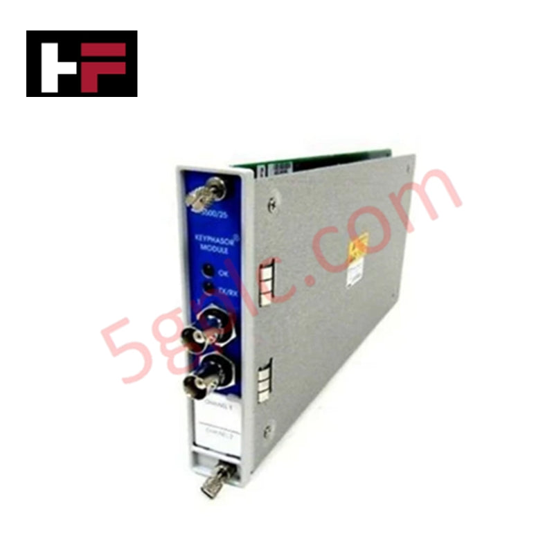
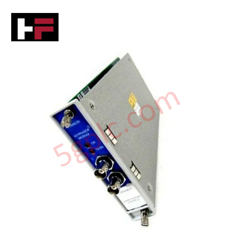
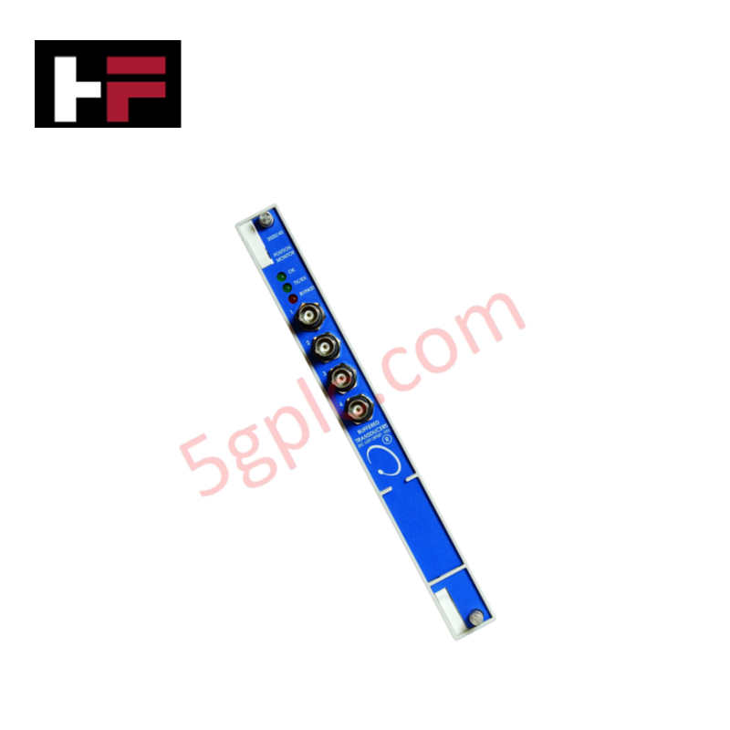
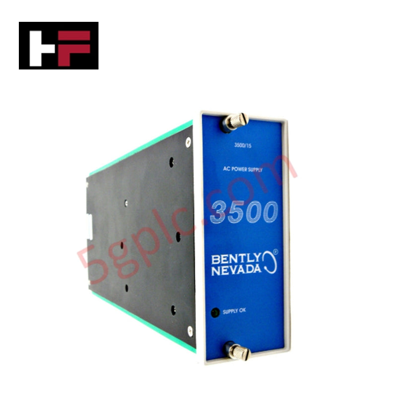
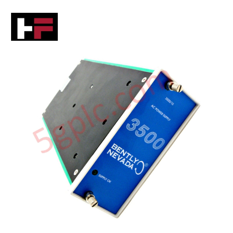
The 3500/25-01-02-01 is an Enhanced Keyphasor Module designed for the Bently Nevada 3500 Machinery Protection System. Operating as a half-height, two-channel unit, it receives input signals from proximity probes or magnetic pickups when the shaft mark aligns with the transducer, converting them into digital Keyphasor timing signals for other monitor modules in the rack.
Signal Processing and System Compatibility
The enhanced module features upgraded Keyphasor signal processing capabilities while maintaining full form, fit, and function compatibility with legacy 3500 Keyphasor modules. In standard rack configurations, the 3500 system accepts up to four Keyphasor signals, or up to eight signals in paired configurations. It serves as the direct replacement module for the older PWA 125792-01 hardware via the upgraded 149369-01 module architecture.
Redundancy and Channel Configuration
For Triple Modular Redundant (TMR) applications requiring redundant phase reference signals, two Keyphasor modules operate in parallel to deliver both primary and secondary Keyphasor signals across the rack backplane. Paired configurations require two successive monitoring positions in upper, lower, or both half-slot locations. When configured with four modules in a paired setup, the system accepts four primary and four backup input channels to provide four independent output channels.
Ordering Options and Physical Construction
The 3500/25-01-02-01 ordering code breakdown designates the following hardware configuration:
- Channel Option (-01): Two 2-channel half-height Keyphasor cards.
- I/O Module Option (-02): I/O module with internal terminations.
- Agency Approval Option (-01): Agency approval option included for certified installations.
| Parameter | Specification |
|---|---|
| Model | 3500/25-01-02-01 |
| Brand | Bently Nevada |
| Product Type | Enhanced Keyphasor Module |
| Number of Channels | Two 2-channel half-height cards (-01) |
| I/O Module Type | Internal Terminations (-02) |
| Agency Approval | Yes (-01) |
| Compatible Transducers | Proximity probes, Magnetic pickups |
| Power Consumption | 3.2 W |
| Input Impedance | 21.8 k ohm minimum |
| Output Impedance | 504 ohm maximum |
| Operating Temperature | -30 deg C to +65 deg C |
| Storage Temperature | -40 deg C to +85 deg C |
Frequently Asked Questions
Q: What input transducers are compatible with the Bently Nevada 3500/25-01-02-01 module?
A: It accepts input signals from standard proximity probes or magnetic pickups to generate digital Keyphasor timing signals.
Q: How is redundancy handled for TMR applications using this module?
A: TMR applications utilize two Keyphasor modules in parallel to supply both primary and secondary Keyphasor signals across the rack backplane.
Q: What older part number does this module replace?
A: The upgraded 149369-01 module architecture used in this unit serves as a direct replacement for the legacy PWA 125792-01 Keyphasor module.
Additional Information
- 100% Genuine Parts: All products are original and authentic, ensuring reliable industrial performance.
- 30-Day Refund Guarantee: Return any in-stock item within 30 days in original, unopened packaging for a full refund (excluding shipping and fees).
- 12-Month Warranty: Covers defects in materials or workmanship; excludes misuse, normal wear, or unauthorized modifications.
- Worldwide Shipping: We ship via USPS, UPS, FedEx, and DHL. Delivery times vary by country and may be subject to customs or import fees.
- Support & Contact: Technical and warranty assistance is available anytime. Contact us here: Contact.
- Purchase Guidance: Check product specifications and compatibility carefully before ordering to ensure proper application.




Tech & Buying Guide

Understanding VFD Mechanical Brake Logic and Control in Industrial Automation
Variable Frequency Drives (VFDs) play a crucial role in modern industrial automation by controlling motor speed, torque, and acceleration. However, high-inertia loads and vertical lifting systems require precise mechanical braking logic to ensure operational safety and prevent equipment damage.

Why Programmable Logic Controllers Drop into Stop Mode: An Expert Analysis
Industrial automation systems rely heavily on Programmable Logic Controllers (PLCs) to maintain uninterrupted production. When a PLC unexpectedly shifts from Run to Stop mode, whole manufacturing lines stall.
As control systems evolve across modern factory automation, understanding the root causes of these interruptions helps engineers minimize costly downtime. This technical guide breaks down why PLCs trip into Stop mode and provides practical strategies to mitigate system faults.

Understanding Root Causes of Unplanned PLC Stop Mode in Industrial Automation
Modern Programmable Logic Controllers manage execution through distinct operational states: Run, Stop, Start-Up, and Hold. During power-up, a controller initializes memory registers within Stop mode before briefly transitioning to Start-Up mode. During this phase, internal self-diagnostics evaluate system integrity across hardware and user programs. If the controller detects no critical faults, it enters Run mode to execute the control program continuously. However, any severe system anomaly forces the CPU back into Stop mode immediately to prevent erratic machine behavior across the plant floor.