


Product Details
Product Overview
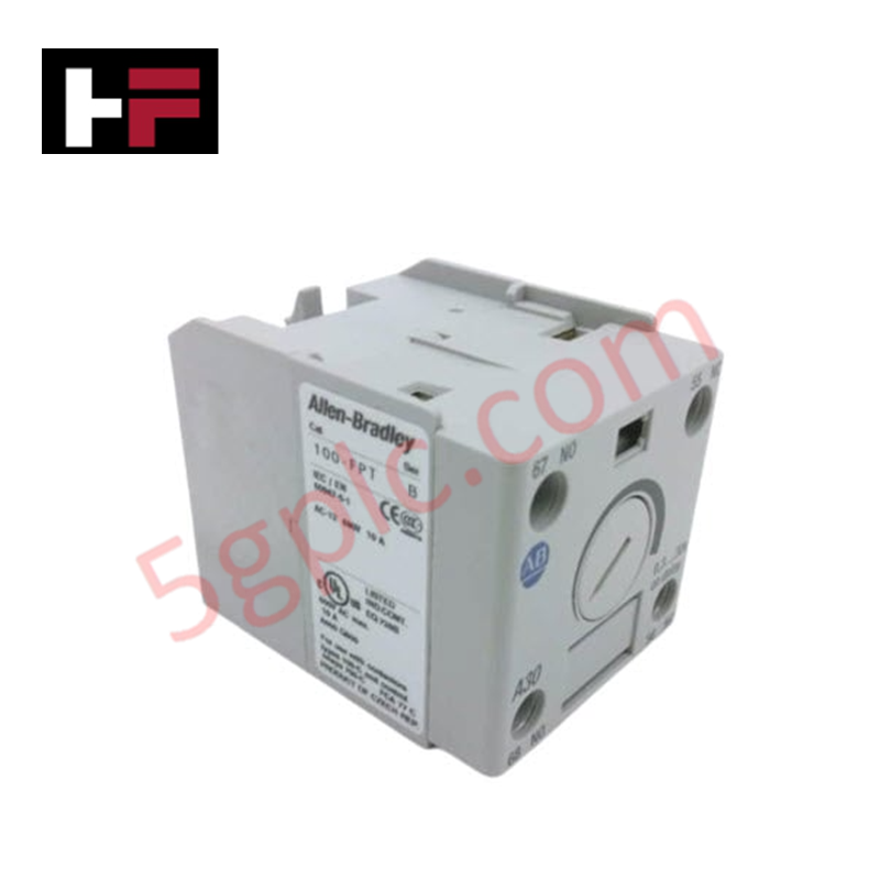
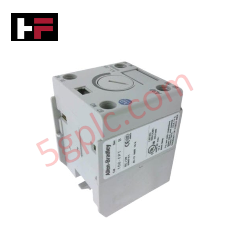
The Allen-Bradley 1794-IFM40F-FS24-2 acts as a high-density pre-wired solution for industrial I/O management. This Fusible Digital Interface Module (IFM) simplifies the connection between PLC I/O cards and field devices by providing integrated circuit protection and clear diagnostic feedback. It specifically supports 16 output channels, each featuring individual fuse protection to prevent localized electrical faults from cascading into system-wide failures. We supply this module as 100% Brand New and Original, ensuring your control cabinet benefits from factory-certified protection and optimal signal conductivity.
Technical Specifications
The 1492-IFM40F-FS24-2 combines 40-pin header connectivity with robust field-side screw terminals.
| Feature | Specification |
| Manufacturer | Allen-Bradley / Rockwell Automation |
| Module Type | Fusible Digital Interface Module (IFM) |
| Output Channels | 16 Channels |
| Input Connector | 40-Pin Male Header |
| Operating Voltage | 10 to 30V AC/DC (24V Nominal) |
| Max Current per Channel | 2 Amps |
| Max Current per Module | 12 Amps Total |
| Visual Diagnostics | Red LED for Blown Fuse Indication (per channel) |
| Wire Size Range | 22 to 12 AWG (0.34 to 4 $mm^2$) |
| Field Terminals | 2 Terminals per Channel |
Engineering Advantages
-
Instantaneous Fault Diagnostics: A dedicated red LED monitors each of the 16 channels. These indicators illuminate immediately upon a fuse blow, allowing maintenance personnel to locate faulted field circuits without manual testing or multimeter probing.
-
Streamlined Cabinet Wiring: The 40-pin header interface allows for a single-cable connection to the PLC I/O module. This "plug-and-play" architecture eliminates hundreds of individual wire terminations, reducing labor costs and minimizing human error during panel assembly.
-
Enhanced Channel Isolation: The hardware provides isolation between channels, preventing ground loops and protecting sensitive PLC electronics from field-side voltage spikes. This architecture ensures that a short circuit in one field device does not compromise the operational integrity of the remaining 15 channels.
-
Heavy-Duty Terminal Capacity: The screw terminals accommodate wire sizes up to 12 AWG. This allows for the use of thicker gauge field wiring to minimize voltage drop over long cable runs, a critical requirement for high-current solenoid and actuator applications.
FAQs
-
What type of cable should I use with the 1492-IFM40F-FS24-2?
You must use a 1492-series pre-wired cable with a 40-pin female connector (such as the 1492-CABLE series). Ensure the cable length and pinout match your specific Allen-Bradley I/O card to maintain signal mapping accuracy.
-
Can I replace the fuses while the module is powered?
While the module allows for easy fuse access, always follow standard industrial safety protocols. We recommend de-energizing the specific field circuit before replacing the fuse to prevent arcing and ensure personnel safety.
-
Does this module support both AC and DC voltages?
Yes. The module operates within a 10 to 30V range for both AC and DC current. However, the LED indicators are specifically optimized for 24V nominal systems to ensure proper brightness for "Blown Fuse" alerts.
-
How does this module handle high-current loads?
Each channel manages up to 2 Amps; however, you must ensure the total current across all 16 channels does not exceed the module's 12 Amp limit. Overshooting this total limit can lead to thermal stress on the internal busbars.
Additional Information
- 100% Genuine Parts: All products are original and authentic, ensuring reliable industrial performance.
- 30-Day Refund Guarantee: Return any in-stock item within 30 days in original, unopened packaging for a full refund (excluding shipping and fees).
- 12-Month Warranty: Covers defects in materials or workmanship; excludes misuse, normal wear, or unauthorized modifications.
- Worldwide Shipping: We ship via USPS, UPS, FedEx, and DHL. Delivery times vary by country and may be subject to customs or import fees.
- Support & Contact: Technical and warranty assistance is available anytime. Contact us here: Contact.
- Purchase Guidance: Check product specifications and compatibility carefully before ordering to ensure proper application.


Tech & Buying Guide

Understanding Dry Contacts in PLC Wiring: An Industrial Automation Guide
Mastering contact switching principles is essential for reliable control panels. Field devices and PLCs interface through dry or wet contacts. This technical guide examines the mechanics of dry contacts, explores their wiring architectures, and evaluates their key advantages in industrial automation.

Ultimate Commissioning Checklist for Industrial Automation Systems: An Engineering Guide
Commissioning is the most decisive phase of an industrial automation project, transforming control hardware and software into an operational facility. Thorough testing prevents costly startup delays and builds customer confidence. This guide covers essential checklists, electrical standards, and best practices.

Redundant Automation Systems: Core Architecture, Business Value, and Technical Advantages
Unplanned downtime poses a major financial threat to process manufacturing. To prevent costly interruptions, engineers deploy redundant PLC and DCS architectures that ensure continuous operation when hardware fails. This technical guide explores redundancy principles, critical system nodes, and real-world scenarios.