










Product Details
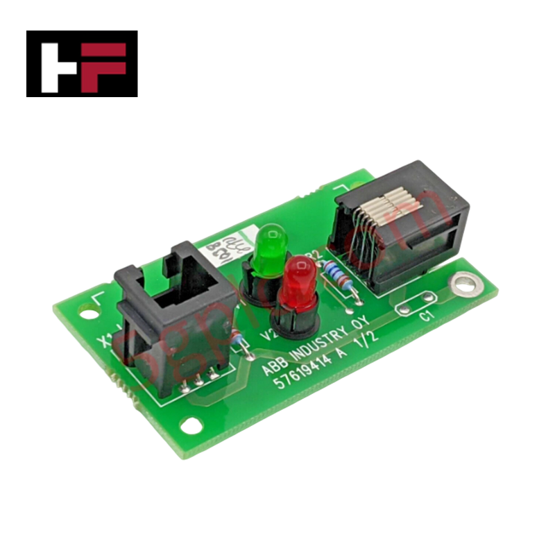
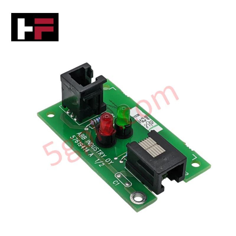
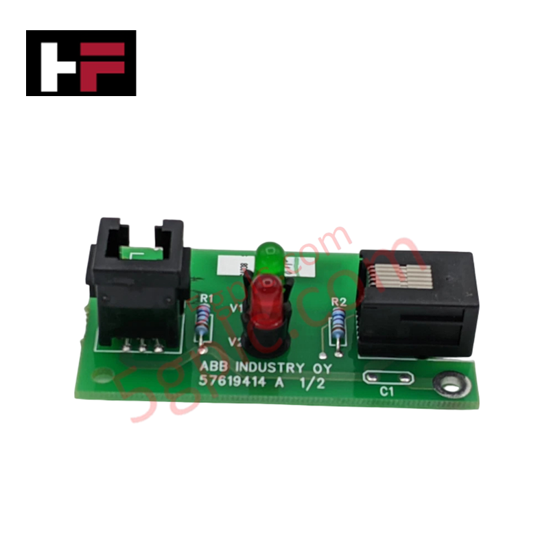
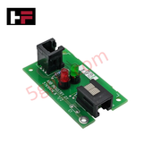
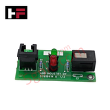
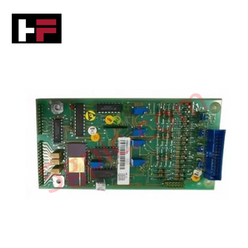
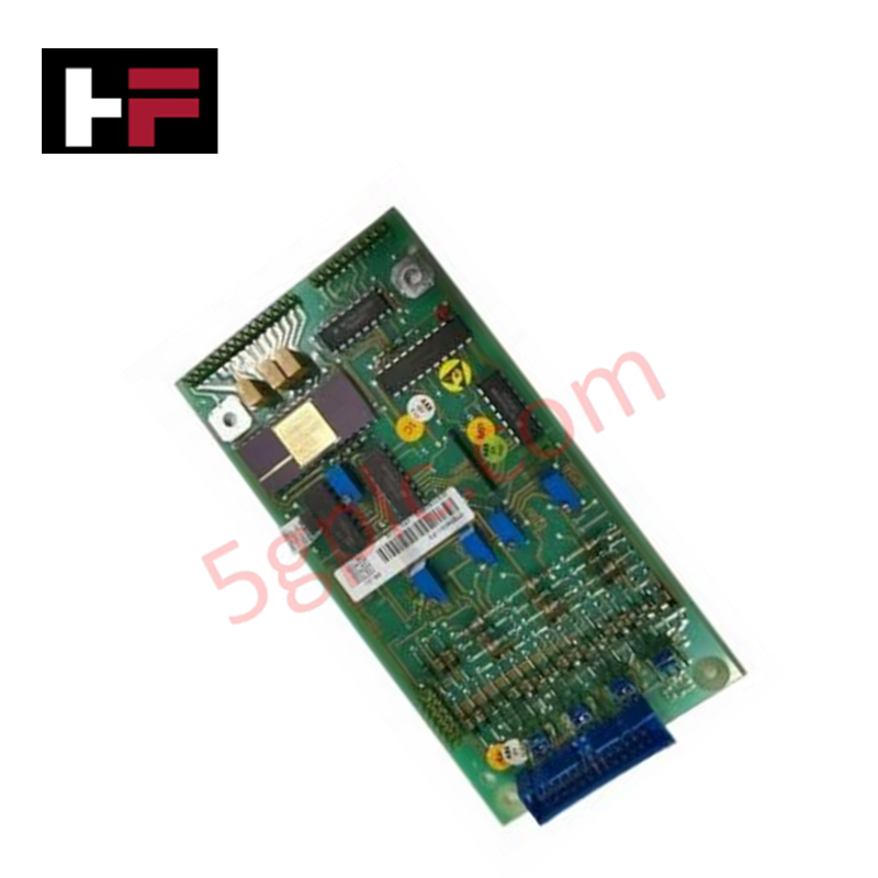
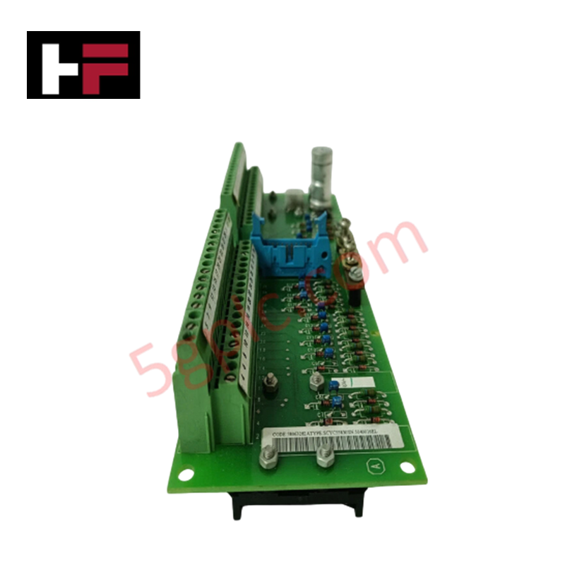
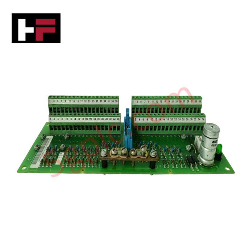
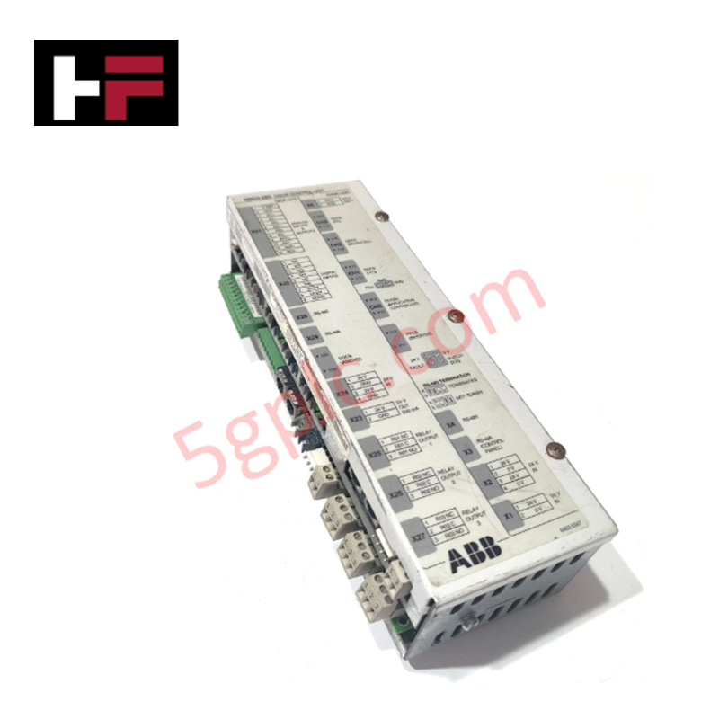
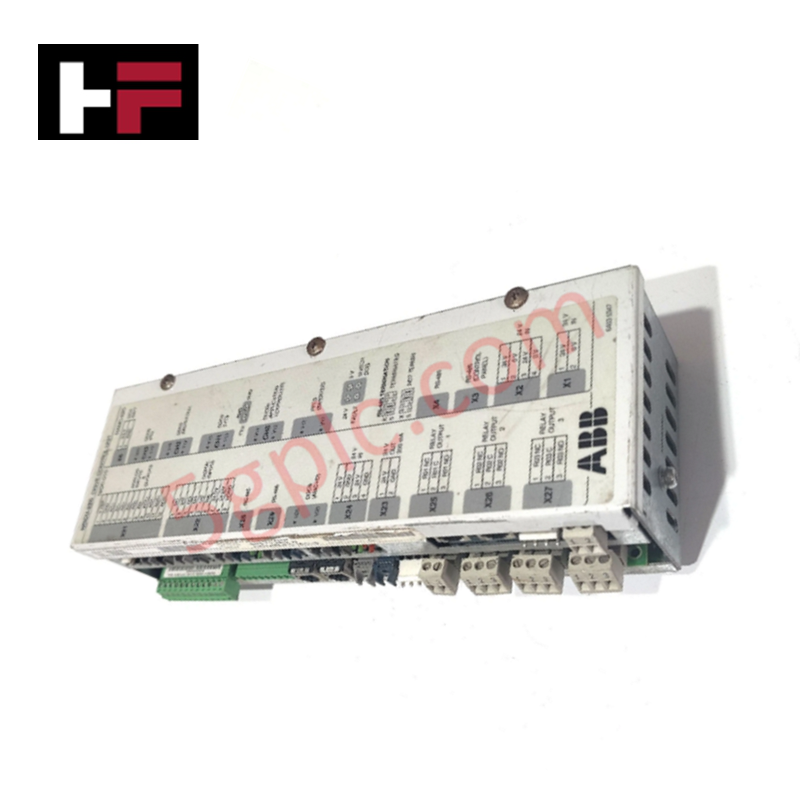
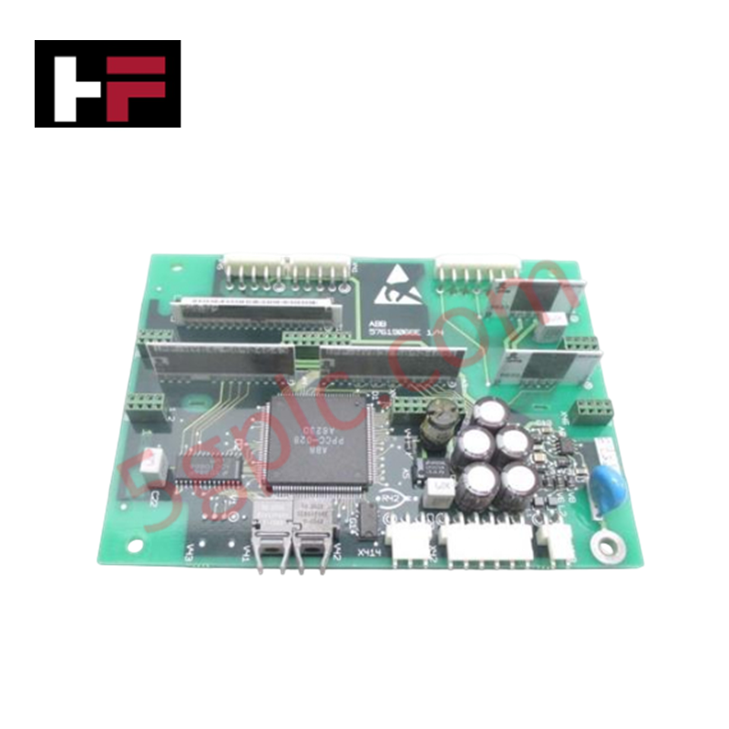
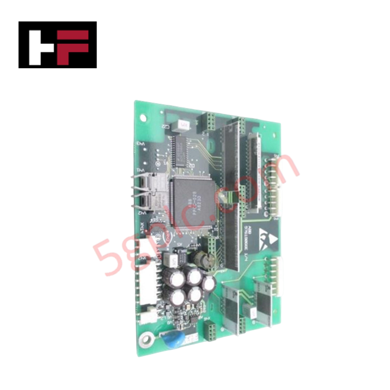
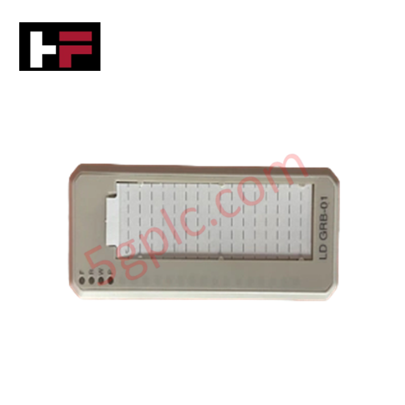
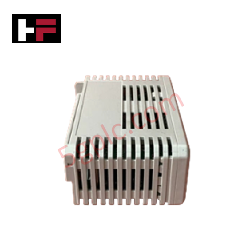
The ABB 57619414 A, also cataloged as the 57619414 A Interface Inverter Board, operates as a dedicated hardware component for diagnostic LED signal indication and communication pass-through within ABB industrial drive chassis.
Hardware Specifications
| Parameter | Specification |
|---|---|
| Model | 57619414 A |
| Brand | ABB |
| Origin | Finland / Switzerland |
| Weight | 0.05 kg |
| Dimensions | 50 mm x 30 mm x 20 mm |
| Operating Temp | 0 to 60 deg C |
| Power Consumption | Direct signal rail low-power draw |
| Board Type | LED Indicator / Interface Extension Board |
| Status Indicators | Dual LED (1 Green, 1 Red) |
| Connector Types | Standard RJ-style pass-through ports |
Backplane Bus Communication Velocity and Firmware Flash Compatibility
The 57619414 A interface inverter board provides real-time state visualization without introducing propagation latency or affecting backplane bus communication velocity across host drive modules. Dedicated green (power/ok) and red (fault/alarm) status LEDs process low-voltage digital state signals directly from the main control unit. Standardized firmware flash compatibility across the parent drive control board ensures synchronized visual diagnostics during dynamic drive startup, commissioning, and fault interrogation cycles.
Frequently Asked Questions
Q: What are the functions of the red and green indicator lights on the 57619414 A board?
A: The green LED indicates nominal supply power and active operational status, while the red LED signals fault triggers, alarm conditions, or communications interlocks within the host drive.
Q: How is physical power supplied to the 57619414 A LED board?
A: Power and diagnostic drive logic signals are provided directly through the multi-pin ribbon cable connection or modular RJ connector attached to the central drive controller.
Q: Does replacing the 57619414 A interface board require software re-flashing?
A: No software flashing is required; the module acts as a passive indicator and connector transition board, allowing direct plug-and-play replacement.
Field Installation Guidelines
- Disconnect incoming line power to the drive subrack and wait at least 5 minutes for intermediate DC bus capacitors to discharge.
- Verify zero potential across main power terminals using a calibrated multimeter prior to touching internal components.
- Wear an ESD wrist strap bonded to functional earth to prevent electrostatic damage to the surface-mount LED and resistor networks.
- Align the 57619414 A circuit board with its chassis mounting standoffs and gently press RJ signal cables into their respective sockets until locked.
- Fasten board retaining screws, restore auxiliary control voltage, and observe LED status lights to confirm system health.
Additional Information
- 100% Genuine Parts: All products are original and authentic, ensuring reliable industrial performance.
- 30-Day Refund Guarantee: Return any in-stock item within 30 days in original, unopened packaging for a full refund (excluding shipping and fees).
- 12-Month Warranty: Covers defects in materials or workmanship; excludes misuse, normal wear, or unauthorized modifications.
- Worldwide Shipping: We ship via USPS, UPS, FedEx, and DHL. Delivery times vary by country and may be subject to customs or import fees.
- Support & Contact: Technical and warranty assistance is available anytime. Contact us here: Contact.
- Purchase Guidance: Check product specifications and compatibility carefully before ordering to ensure proper application.
Tech & Buying Guide

Top 5 Operational Advantages of HMIs in Modern Factory Automation

Importance of Safety Barriers in PLC and DCS Control Systems
