


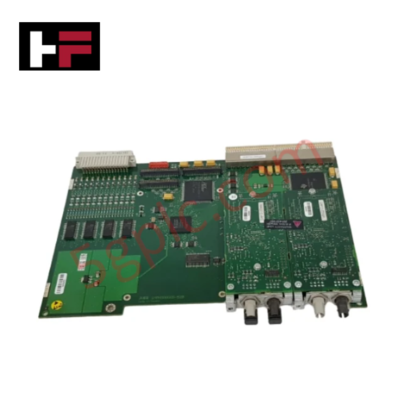
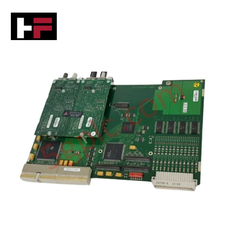
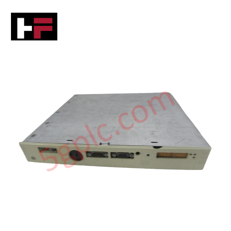
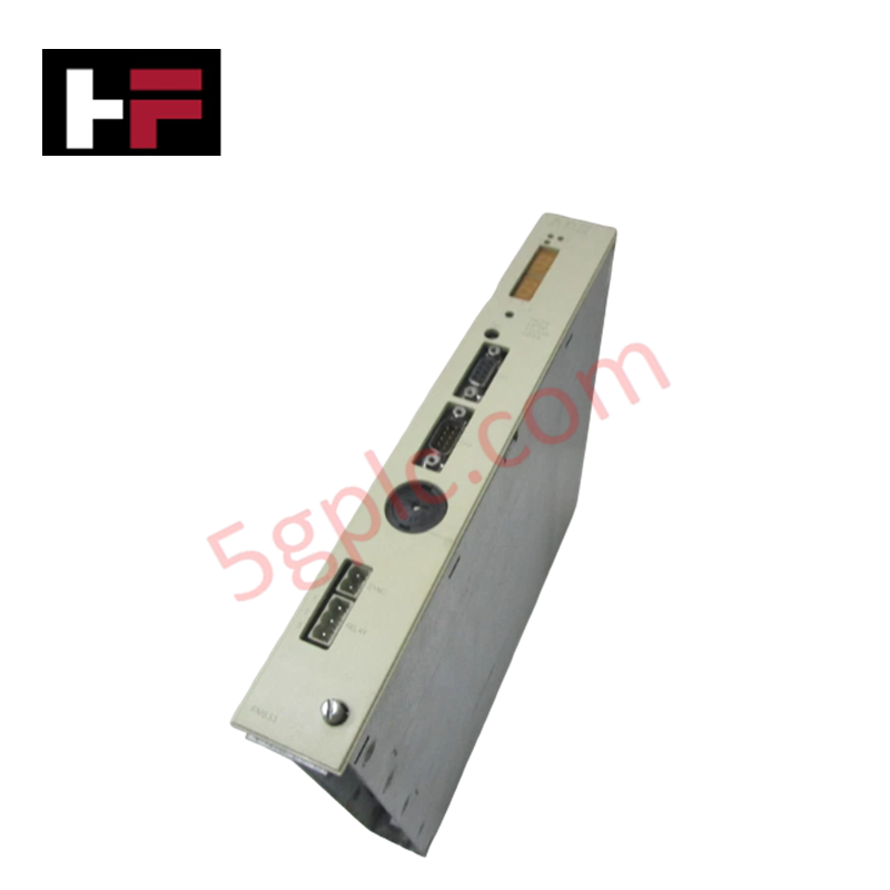
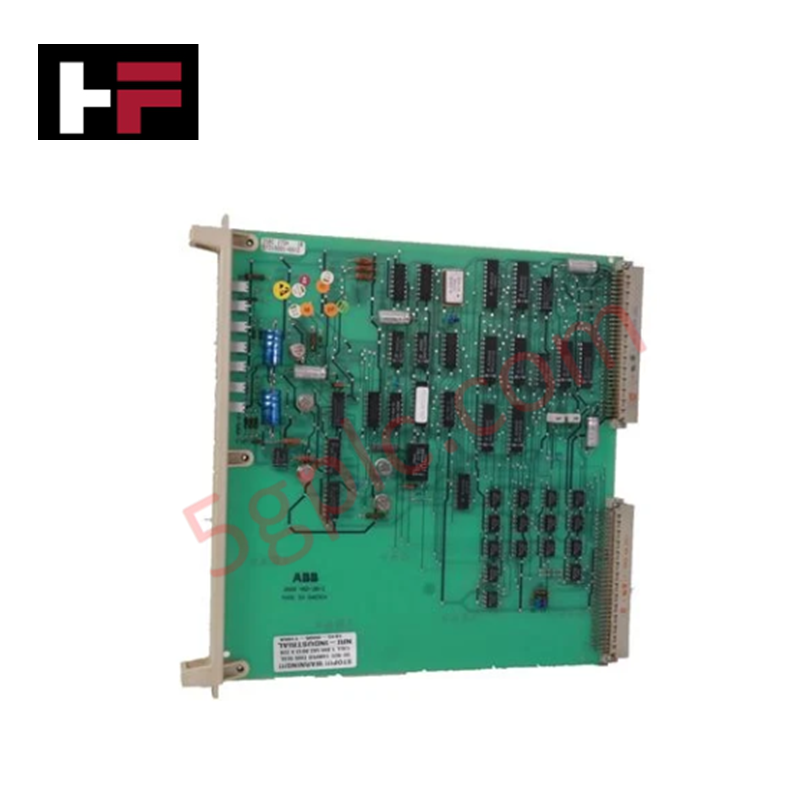
Product Details
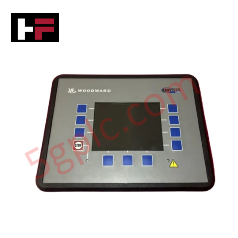
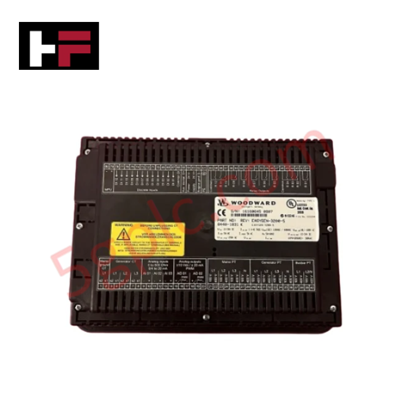
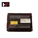
Configured for genset management and synchronization, the Woodward 8440-1831 (8440-1831 Series Controller Unit) provides direct physical/electrical execution of generator monitoring and protection tasks.
Hardware Specifications
| Parameter | Specification |
|---|---|
| Model | 8440-1831 |
| Brand | Woodward |
| Origin | Not specified |
| Weight | 2150 g |
| Dimensions | 282 x 217 x 99 mm |
| Operating Temp | Not specified |
| Power Consumption | Max 14 W |
| Measuring Frequency | 40 - 85 Hz |
| Input Resistance | 2.0 M Ohm |
| Power Supply | 8 - 40 VDC |
V/Hz and Field-Oriented Vector Control
The 8440-1831 controller integrates FlexIn technology to manage various analog input signals, including resistive senders and 0/4-20 mA loops. This flexibility enables the unit to execute precise generator control loops, maintaining stable voltage and frequency regulation. The controller is designed to support field-oriented vector control logic, ensuring accurate phase matching during multiple-unit mains applications. Proper configuration of the MCB release and reply signals is required to maintain synchronization and harmonic distortion suppression across interconnected genset platforms.
Frequently Asked Questions
Q: Are the relay outputs on the 8440-1831 galvanically isolated?
A: Yes, the relay outputs are isolated to prevent electrical interference and protect the internal control circuitry from field-side voltage spikes.
Q: What are the requirements for the FlexIn analog inputs?
A: The three FlexIn analog inputs are software-configurable for VDO, resistive, or 0/4-20 mA sender types. Ensure that the sensor ground configuration (one-pole or two-pole) matches the controller's input settings to prevent signal offsets.
Field Installation Guidelines
- Handling: The housing is constructed of high-impact plastic; exercise caution during mounting to prevent mechanical stress or cracking of the enclosure.
- Mounting: Utilize the specified 282 x 217 x 99 mm footprint for panel integration. Ensure adequate clearance for terminal connections and heat dissipation.
- Wiring: For multiple-unit applications, ensure all connected controllers receive identical mains voltage and current feedback signals to prevent synchronization errors.
- Signal Shielding: Terminate cable shields at the designated cabinet ground point. Keep analog signal cabling separate from high-current AC output lines to avoid induced electromagnetic noise.
- Validation: Verify the DC power supply is within the 8-40 VDC range before commissioning. Confirm that the measuring frequency range (40-85 Hz) is compatible with the connected generator system.
Additional Information
- 100% Genuine Parts: All products are original and authentic, ensuring reliable industrial performance.
- 30-Day Refund Guarantee: Return any in-stock item within 30 days in original, unopened packaging for a full refund (excluding shipping and fees).
- 12-Month Warranty: Covers defects in materials or workmanship; excludes misuse, normal wear, or unauthorized modifications.
- Worldwide Shipping: We ship via USPS, UPS, FedEx, and DHL. Delivery times vary by country and may be subject to customs or import fees.
- Support & Contact: Technical and warranty assistance is available anytime. Contact us here: Contact.
- Purchase Guidance: Check product specifications and compatibility carefully before ordering to ensure proper application.


Tech & Buying Guide

Understanding Dry Contacts in PLC Wiring: An Industrial Automation Guide
Mastering contact switching principles is essential for reliable control panels. Field devices and PLCs interface through dry or wet contacts. This technical guide examines the mechanics of dry contacts, explores their wiring architectures, and evaluates their key advantages in industrial automation.

Ultimate Commissioning Checklist for Industrial Automation Systems: An Engineering Guide
Commissioning is the most decisive phase of an industrial automation project, transforming control hardware and software into an operational facility. Thorough testing prevents costly startup delays and builds customer confidence. This guide covers essential checklists, electrical standards, and best practices.

Redundant Automation Systems: Core Architecture, Business Value, and Technical Advantages
Unplanned downtime poses a major financial threat to process manufacturing. To prevent costly interruptions, engineers deploy redundant PLC and DCS architectures that ensure continuous operation when hardware fails. This technical guide explores redundancy principles, critical system nodes, and real-world scenarios.