


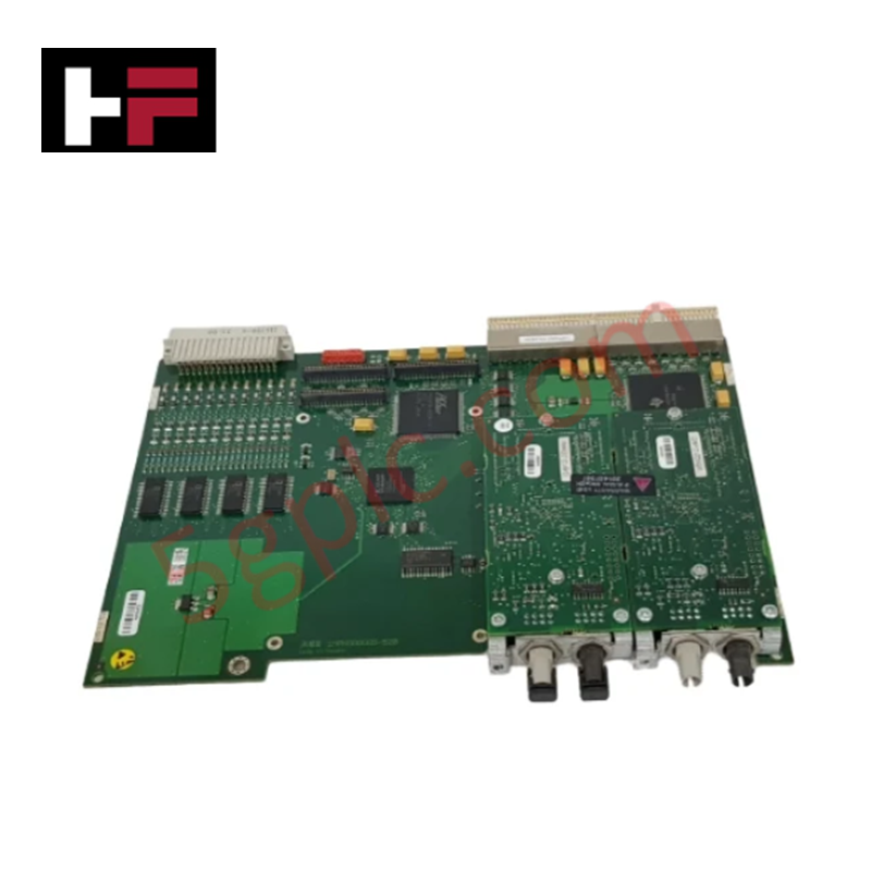
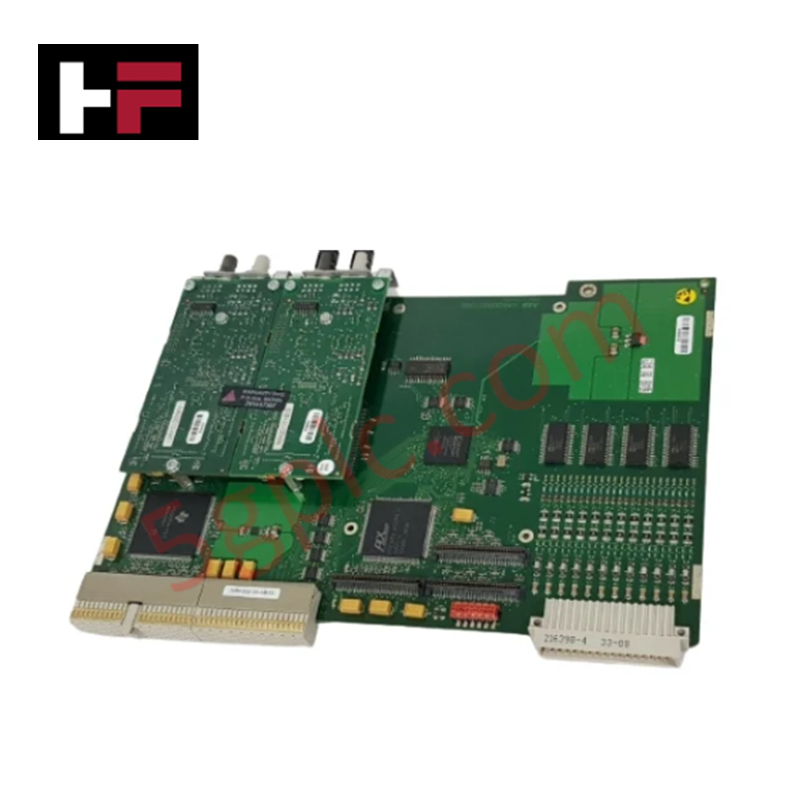
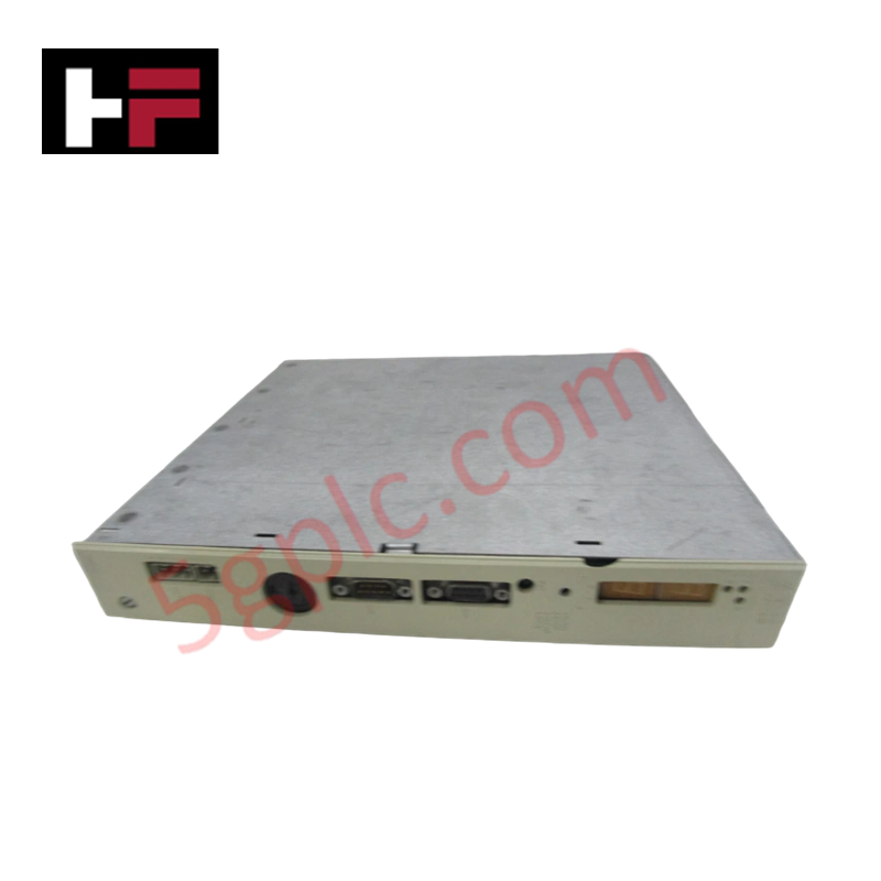
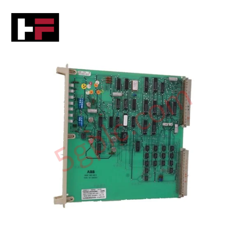
Product Details
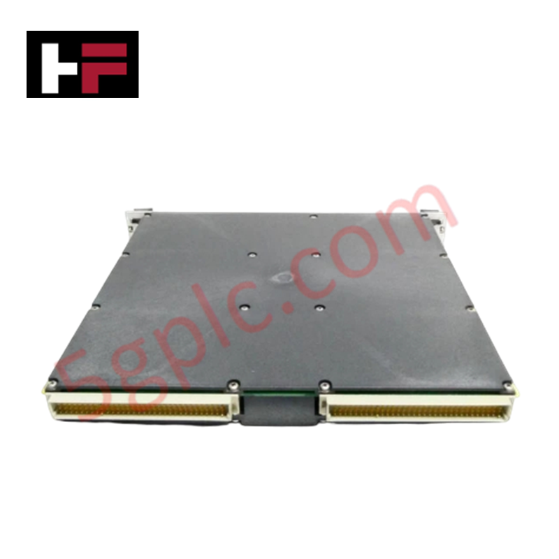
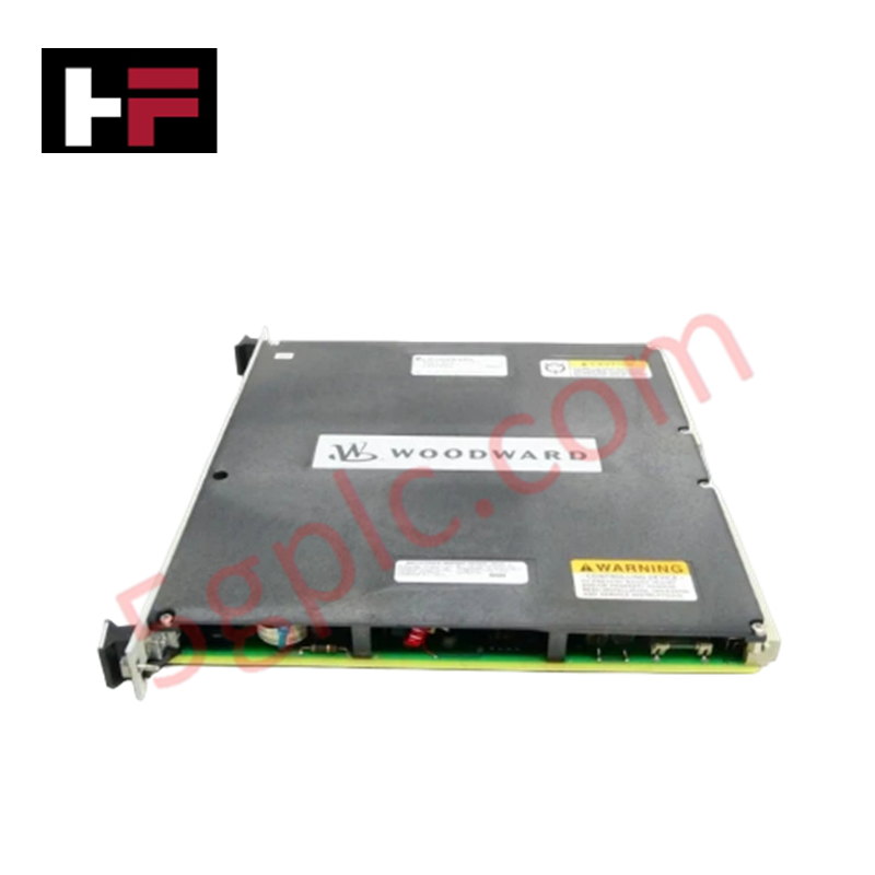
Configured for proportional or integrating actuator control in MicroNet systems, the Woodward 5501-429 (25mA Version Actuator Controller) provides direct electrical execution of dual-channel hydromechanical or pneumatic actuator management.
Hardware Specifications
| Parameter | Specification |
|---|---|
| Model | 5501-429 |
| Brand | Woodward |
| Origin | Not specified |
| Weight | Less than 2 lbs |
| Dimensions | 10.25 in x 9.75 in x 1 in |
| Operating Temp | Not specified |
| Power Consumption | +5 V at 0.5 A, +24 V at 1 A |
| Output Current | 25 mA (Nominal) |
| Max Load Resistance | 10/30 mA |
| Current Read back Tolerance | 5 % of full scale |
Actuator Loop Feedback Response and Thermal Heat Sink Dissipation Profiles
The 5501-429 utilizes model-based control to regulate actuator position via integrated LVDT or RVDT feedback loops. The module enforces strict actuator loop feedback response by monitoring excitation, feedback voltage, and driver current status, ensuring compliance with specified control setpoints. Internal diagnostics provide hardware-level fault detection, including CPU communication status and microcontroller operational integrity. The module is designed to operate within MicroNet chassis thermal limits; however, consistent adherence to airflow guidelines is required to maintain the module's thermal heat sink dissipation profiles during high-duty actuator modulation. Any deviation in current read back exceeding the 5% tolerance threshold triggers an internal alarm, signaling a potential feedback mismatch or actuator drive degradation.
Frequently Asked Questions
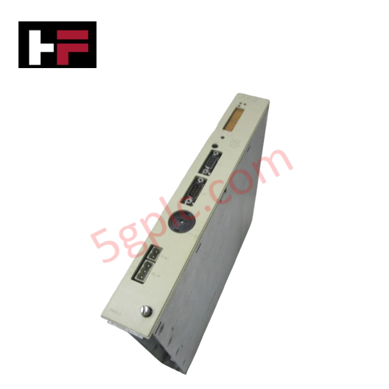
Q: How can the front-panel LED be interpreted for system troubleshooting?
A: A solid red LED indicates a loss of communication between the controller and the CPU module. A flashing red LED signifies an internal hardware error, necessitating immediate module replacement.
Q: What are the primary feedback device compatibility requirements for this module?
A: The 5501-429 supports one or two position feedback devices per channel, specifically LVDT or RVDT sensors, which are configured via the MicroNet control software to map position to the actuator demand.
Field Installation Guidelines
- Mounting: Slide the module into the control chassis card guides and seat firmly into the motherboard connectors. Utilize the top and bottom extraction handles to ensure the connector pins are fully engaged.
- Cabling: Utilize a MicroNet low-density discrete cable for all module communications. Ensure signal shielding is maintained to ground to prevent noise injection into the LVDT/RVDT feedback signals.
- Powering: Verify that the +5 V and +24 V power rails are within nominal tolerances before applying power to the module. Ensure the external power supply is capable of sustaining the 1 A current requirement on the 24 V rail.
- Commissioning: Following physical installation, confirm the module is recognized by the CPU via the system interface. If the red LED remains solid, verify the backplane ribbon cable integrity and CPU communication configuration.
Additional Information
- 100% Genuine Parts: All products are original and authentic, ensuring reliable industrial performance.
- 30-Day Refund Guarantee: Return any in-stock item within 30 days in original, unopened packaging for a full refund (excluding shipping and fees).
- 12-Month Warranty: Covers defects in materials or workmanship; excludes misuse, normal wear, or unauthorized modifications.
- Worldwide Shipping: We ship via USPS, UPS, FedEx, and DHL. Delivery times vary by country and may be subject to customs or import fees.
- Support & Contact: Technical and warranty assistance is available anytime. Contact us here: Contact.
- Purchase Guidance: Check product specifications and compatibility carefully before ordering to ensure proper application.


Tech & Buying Guide

Understanding Dry Contacts in PLC Wiring: An Industrial Automation Guide
Mastering contact switching principles is essential for reliable control panels. Field devices and PLCs interface through dry or wet contacts. This technical guide examines the mechanics of dry contacts, explores their wiring architectures, and evaluates their key advantages in industrial automation.

Ultimate Commissioning Checklist for Industrial Automation Systems: An Engineering Guide
Commissioning is the most decisive phase of an industrial automation project, transforming control hardware and software into an operational facility. Thorough testing prevents costly startup delays and builds customer confidence. This guide covers essential checklists, electrical standards, and best practices.

Redundant Automation Systems: Core Architecture, Business Value, and Technical Advantages
Unplanned downtime poses a major financial threat to process manufacturing. To prevent costly interruptions, engineers deploy redundant PLC and DCS architectures that ensure continuous operation when hardware fails. This technical guide explores redundancy principles, critical system nodes, and real-world scenarios.