


Product Details
Product Overview
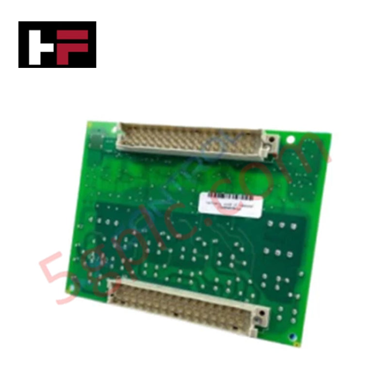
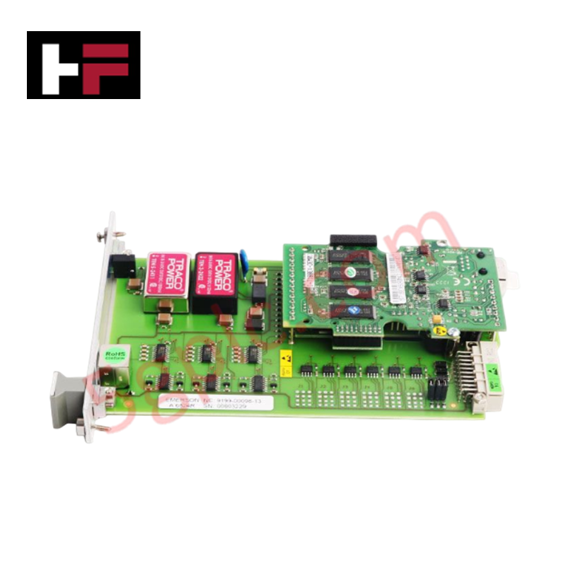
The IS200WROBH1AAA functions as a high-integrity Relay Fuse and Power Sensing (WROB) board within the General Electric Mark VIe control architecture. This Brand New original component provides critical circuit protection and diagnostic feedback for relay-driven outputs. By monitoring the status of individual fuses and power distribution paths, it ensures that the turbine control system maintains precise command execution. It serves as a vital expansion for PDIO modules, bridging the gap between digital logic and field-side power actuation.
Technical Specifications
The IS200WROBH1AAA utilizes precision sensing circuits to monitor relay coil health and fuse integrity.
| Feature | Specification Details |
| Manufacturer | General Electric (GE) |
| Series | Mark VIe |
| Functional Acronym | WROB |
| Fuse Rating | 3.15 Amperes |
| Relay Type Compatibility | TRLY Series |
| Redundancy Modes | Simplex, Redundant, or TMR |
| TMR Terminal Support | TDBTH2, TDBTH4, TDBTH6 |
| Weight | 0.2 kg |
| Dimensions | 16 cm x 12 cm x 6 cm |
Engineering Advantages
-
Triple Modular Redundancy (TMR) Support: The IS200WROBH1AAA fully supports TMR architectures when paired with TDBTH2, TDBTH4, or TDBTH6 terminal boards. This ensures that a single point of failure within a fuse or relay path does not compromise the overall turbine safety loop.
-
Integrated Overcurrent Protection: Each circuit utilizes a 3.15A fuse to isolate faults locally. This design prevents a short circuit in a single field solenoid or relay from pulling down the entire 24V DC power bus, thereby maintaining system availability.
-
Real-Time Power Sensing: The board actively senses the presence of voltage downstream of the fuse. It reports blown-fuse conditions directly to the Mark VIe controller, allowing maintenance teams to identify and replace faulty components without manual troubleshooting.
-
Ultra-Compact Footprint: Weighing only 0.2 kg and measuring 16x12x6 cm, this board facilitates high-density installation in space-constrained control cabinets. It mounts directly to parent boards (like the TDBS or TDBT), eliminating the need for additional DIN rail space or complex interconnecting looms.
FAQs
-
Is the IS200WROBH1AAA a direct replacement for the IS200WROBH1A?
Yes. The "AAA" suffix denotes the specific revision artwork and firmware version. This Brand New unit maintains full backward compatibility with the H1A base model while incorporating GE’s latest component reliability standards.
-
How does the board behave in a TMR configuration?
In TMR mode, the WROB board facilitates the "voting" of signals. It connects to three separate I/O packs through the TDBT board, ensuring that two-out-of-three packs must agree on a command before the final relay output changes state.
-
What are the primary indicators of a fuse failure?
The board communicates fuse status through the Mark VIe IONet. Within your HMI or ToolboxST software, the "Fuse Status" diagnostic bit will toggle, identifying the specific 3.15A fuse that requires replacement.
-
Can I use this board with 125V DC relay circuits?
The IS200WROBH1AAA typically manages low-voltage DC power distribution for relay coils. Always refer to the GEH-6721 system manual to verify specific voltage limits for your terminal board and relay combination.
Additional Information
- 100% Genuine Parts: All products are original and authentic, ensuring reliable industrial performance.
- 30-Day Refund Guarantee: Return any in-stock item within 30 days in original, unopened packaging for a full refund (excluding shipping and fees).
- 12-Month Warranty: Covers defects in materials or workmanship; excludes misuse, normal wear, or unauthorized modifications.
- Worldwide Shipping: We ship via USPS, UPS, FedEx, and DHL. Delivery times vary by country and may be subject to customs or import fees.
- Support & Contact: Technical and warranty assistance is available anytime. Contact us here: Contact.
- Purchase Guidance: Check product specifications and compatibility carefully before ordering to ensure proper application.


Tech & Buying Guide

Preventing Spurious Trips in Emergency Stop Systems: A Technical Guide
In industrial automation, the Emergency Stop (E-Stop) pushbutton is the ultimate safety line. However, relying on a single Normally-Closed (NC) contact can sometimes lead to unexpected spurious trips. As a control systems engineer, I have seen these nuisance trips halt entire production lines, causing significant downtime. Understanding why these components fail and how to implement robust architecture is essential for any reliable DCS or PLC-based safety system.

Sequencing Induction Motor Control with PLC Logic: Best Practices
In modern industrial automation, controlling a group of induction motors requires precision and safety. Uncontrolled simultaneous startup of multiple large motors often causes significant voltage dips, potentially triggering protective trips. Therefore, implementing a sequential startup and shutdown strategy is essential. This approach minimizes inrush current and ensures the system operates within established power constraints. A robust PLC program serves as the ideal engine for orchestrating these sequences.

Mastering PLC Programming: Best Practices for Robust Industrial Automation
Writing clean PLC code requires discipline, especially regarding memory management. Avoid overusing SET and RESET instructions, as they often complicate debugging. If multiple rungs control the same bit, troubleshooting becomes a nightmare. Instead, focus on energizing a bit in only one location. If your logic requires complex conditions, use branches within a single rung. This approach keeps your code readable, maintainable, and significantly easier to audit during downtime.